
Contents
- Introduction
- Background
- Architecture Overview
- The Application
- Setting up Azure
- Connecting the Services
- The Application (Demo)
- TL;DR
- Points of Interest
- References
- History
Introduction
In this article we discuss the application BabyZen. The basic idea is to monitor important quantities defining the environment of a baby. These quantities can be correlated with measured (or recorded) disturbances of a baby's everyday life. Using Microsoft Azure's machine learning capabilities we can deduce recommendations on how to improve a baby's life by minimizing negative disturbances. Another positive side effect is an increased security against the sudden infant death syndrome and several childhood illnesses, which comes from optimizing the environment according to current health studies.
The name BabyZen encodes an important aspect of our application. The word Zen is derived from the Japanese pronunciation of the Middle Chinese word ? (d?jen) (pinyin: Chán), which in turn is derived from the Sanskrit word dhyana. Zen can be loosely translated as "meditative state"[1]. The aim of our IoT application is to ensure optimal circumstances for the baby to enter such a satisfactory state free of complaints. The Microsoft Azure cloud helps us by providing the infrastructure, platform and services, which make the Internet of Things possible. We combine personally collected data and the results of highly-recognized studies conducted by well-known medical centers, such as the ones given in [2]-[4], with an evaluation by Machine Learning algorithms, which run on the Azure Machine Learning workspace.
The article first goes into some detail about the background of the application and the device, which delivers the real-time data stream. Although we spend quite some time on explaining the components of the device and their interconnection, we will not give step-by-step instructions on building and programming it. After all, the focus of this article lies on the software designed for an IoT application within the Azure framework. A detailed description of the hardware internals would go beyond the scope of the article. After the first section we provide a short overview of the architecture, which elaborates on the different sub-modules and the communication paths. The next three sections explain the application (an ASP.NET MVC webservice), our used Azure services (mainly mobile backend, machine learning and websites) and the connection between Azure and our application in detail. Finally we will talk about some major problems as well as possible solutions.
Background
Motivation and Vision
In this section we first expound our motivation to participate in the Microsoft Azure IoT Contest and outline the basic ideas behind our project. Subsequently we explain the device in detail by elaborating on its components and how they are connected to each other.
Increasing connectivity has triggered one of the biggest changes in the way we interact with our environment during the last decades. After the rapid developments leading to web 2.0, we believe that the Internet of Things (IoT) will have a similar impact on our daily lives. In our opinion it is currently one of the most innovative sectors both in hardware and software design. Hence many appealing and also powerful solutions for fast and simple prototyping have been made available recently. On the hardware side, for instance, there are single-chip wireless microcrontrollers from Texas Instruments with built in Wi-Fi specifically designed for IoT applications. On the software side, Azure provides powerful tools for web hosting and databases combined with proper analysis features like Azure machine learning. Along with the back-end comes the possibility to present the content via mobile apps, websites and RemoteApp. It is essentially tailored to fit the needs of any IoT project. Of course this list is far from complete.
Enabled by the Internet of Things, self-tracking and home automation are amongst the major buzzwords in tech-blogs and magazines nowadays. IoT technologies are heavily used to maintain a healthy life-style and help us to live more environmentally conscious, for example by monitoring our homes, saving power and decreasing CO2 emission. The thought of combining these two ideas led us the concept of BabyZen. While it is straight forward to enhance our own wellbeing, it is harder to do so for babies. They have no means of conveying precise causes of discomfort. Although parents develop an astonishing gut feeling for what their child could complain about, in the end often times one can only guess, whether a baby is truly satisfied with its environment. BabyZen helps providing an ideal environment by tracking all relevant parameters, such as temperature, humidity, CO2 level, ambient light and noise, thereby learning about the dependence of the baby's wellbeing on those factors. Finally BabyZen generates recommendations on how to improve the situation. The ultimate goal is to maintain optimal conditions for the baby's development. In a further step we include the baby's body temperature and heart-rate to render the data set even more complete and further improve the recommendations.
In our application we primarily try to make extensive use of the excellent solutions provided by Azure to create IoT applications. Thereby we reduce communication issues between the different components to a minimum and enjoy the luxury of getting immense functionality out-of-the-box. The architecture is centered around a mobile service hosted by Azure. It is responsible for receiving preprocessed sensor data via event hubs and communicating with Azure's machine learning tools. Moreover, it provides the user interface in the form of a website. Internally, the machine learning solution resorts to an Azure SQL database and the increasingly popular R-language for statistical analysis. While the software side is explained in detail in the following sections, we now focus on the device.
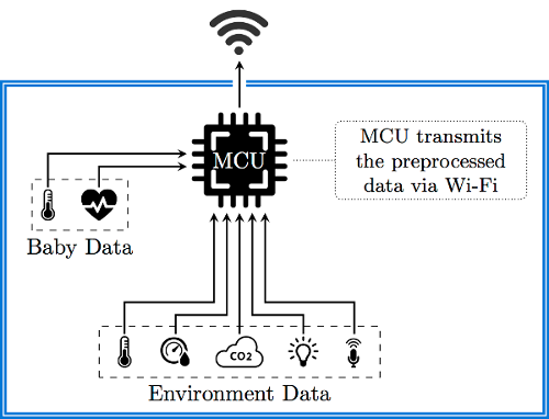
We use a powerful, battery sourced single IC microcontrolling unit to collect and preprocess data from various low-power sensors, which record the temperature, humidity, CO2 content, ambient light, sound pressure and possibly even the heart-rate of the baby. The sensors communicate with the MCU via different channels such as I2C, GPIO, ADCs and others. The preprocessed data is then sent to the Azure web interface via Wi-Fi. In the following, we describe the different hardware components of the device in more detail.
Here is a quick overview over a subset of the components we use:
- MCU (CC3200MOD)[5]
- Temperature, Humidity (HDC1000)[6]
- Ambient Light (OPT3001)[7]
- Gas (LMP91051)[8]
- Heart rate (AFE4400)[9]
A reasonably detailed description of these parts is mandatory for the understanding of how the relevant information is actually obtained by the sensors and then transmitted to our application. The section about the HDC1000 also features a short introduction to the I2C bus, which is very important and a quasi-standard for serial communication in embedded systems. We thereby want to encourage software engineers not to be afraid of low-level programming and simple circuit design, because those skills are often required for IoT projects.
Microcontroller Unit
Let us start out with the center piece, the microcontroller unit (MCU). Here we've decided to use the CC3200MOD from Texas Instruments. It is specifically designed for IoT and general low-power Wi-Fi applications and is industry's first FCC, IC, CE, and Wi-Fi certified single-chip controller module with built in Wi-Fi connectivity. Hence we fulfill all safety standards concerning electromagnetic inference. It integrates all required system-level hardware components and supports TCP/IP and TLS/SSL stacks, HTTP server, and multiple Internet protocols. It features a powerful 256-bit encryption engine for secure connection and supports WPA2 as well as WPS 2.0. At its heart lies a powerful ARM Cortex-M4 operating at 80MHz with up to 256kB of RAM.
The MCU features numerous serial and parallel ports, reaching from GPIOs to specific fast parallel camera interfaces and multichannel serial audio ports, general purpose timers, ADCs and much more. We only elaborate on the interfaces used by sensors later on. Most important to us is the fully integrated Wi-Fi connectivity with a dedicated ARM MCU to completely offload the host MCU with an 802.11 b/g/n radio, which enables fairly simple prototyping even without prior Wi-Fi experience. The following figure gives an overview of the integrated hardware.
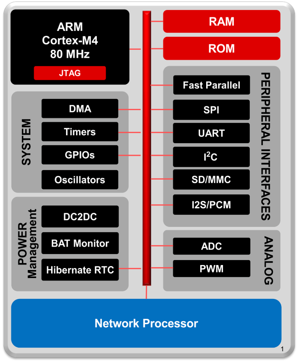
As already mentioned the software stack is also quite impressive. Especially for IoT applications we get a highly tuned and specialized basis, which contains everything we need to connect to the cloud. The following figure illustrates the provided software components.
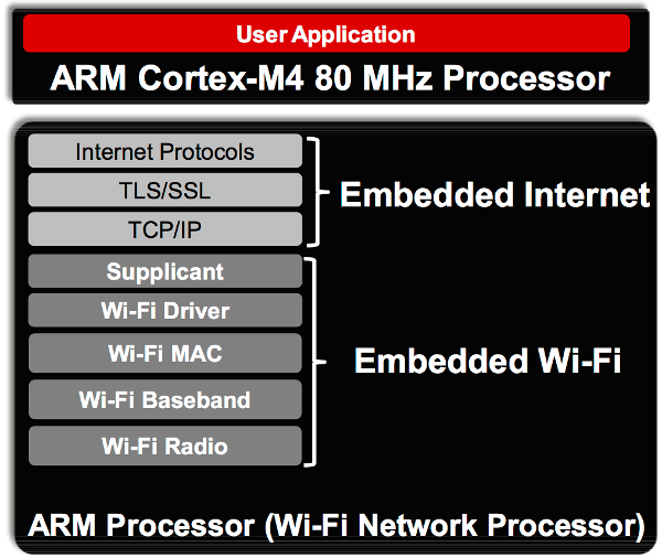
In our application we use the MCU mounted on TI's CC3200MOD LaunchPad[10]. Alongside with the CC3200MOD it features an on-board antenna with U.FL connector as well as some sensors and buttons. The board is USB powered and allows for debugging via JTAG and backchannel UART by FTDI. Thus we can connect it directly to a computer for programming and monitoring. For commercial use, one would replace the LaunchPad by a more minimalistic, custom made PCB, because many helpful features of the LaunchPad are unnecessary once the device is running.
Temperature and Humidity
For temperature and humidity measurements we use TI's HDC1000 sensor. It is a low-power, high accuracy digital humidity and temperature sensor. With up to 14-bit resolution it records relative humidity in the full range from 0% to 100% and temperatures in a range from -40°C to 85°C with excellent accuracy of ±3% and ±0.2°C respectively. Because there is no point in sampling temperature and humidity at higher rates than about 0.1Hz and each conversion of both values at maximal resolution of 14 bits takes less than 15ms, the sensor will spend most of the time in sleep mode with a typical current consumption of only 110nA. Thereby power consumption is reduced to a minimum.
The HDC1000 is connected to the microcontrolling unit through an I2C interface, which renders communication especially simple. We only connect the two standard I2C signal pins SCL for the clock and SDA for serial data transfer. (In our device we also connect the DRDYn pin to the MCU. However, one could also connect that one directly to ground without seriously restricting the functionality.) For pedagogical reasons let us elaborate on the I2C protocol in more detail for this specific, but still rather generic example. In the final device we have more sensors connected to the I2C bus. Since only minor details change from one sensor to the other, we give a detailed explanation only for the HDC1000.
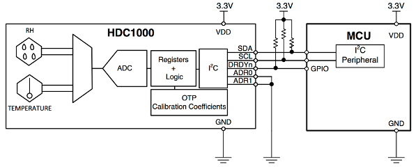
The I2C interface is a rather simple serial computer bus, which we use with a single master (MCU) and multiple slaves (HDC1000, OPT3001), although it even allows for multiple masters also. (For simplicity, in the following explanation we assume that the HDC1000 is the only slave.) As already mentioned, the MCU and the sensor are connected only via two open-drain lanes, the serial data line (SDA) and the serial clock line (SCL). (Again, the DRDYn pin can, but does not have to be connected.) Each slave in the bus has a unique 7-bit address, which is used by the master to select different components. As shown in the figure above, the HDC1000 has two pins called ADR0 and ADR1, which allow to switch between different addresses, see the table below.
Remember that the address has to be unique. If, for example, we want to use several HDC1000s on the same bus, we could externally assign the address 1000000 to the first one, 1000001 to the second one and so on. In this way one can connect up to four identical sensors to the same bus without running into troubles due to non-unique addresses. In our application the two ADR pins are hard-wired to ground or supply voltage levels. The remaining pin DRDYn is operated by the sensor to indicate that it has performed a measurement and that the data is ready to be read by the MCU. We will come to that later.
| ADR1 | ADR0 | 7-bit address |
|---|---|---|
| 0 | 0 | 1000000 |
| 0 | 1 | 1000001 |
| 1 | 0 | 1000010 |
| 1 | 1 | 1000011 |
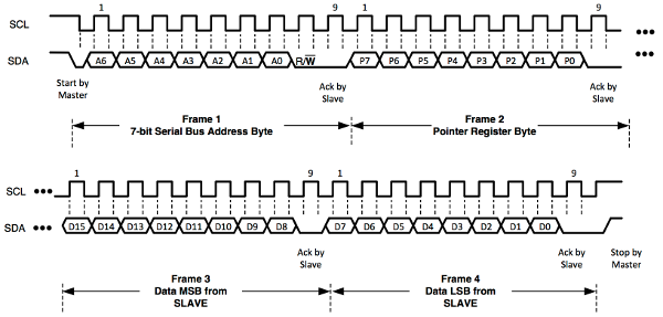
As usual, the communication starts in the master transmit mode, i.e. the master sends signals to the slave. Following the specification of the I2C protocol, the master transmits a start bit followed by the 7-bit address of the slave it wants to talk to on the SDA line. Right after the address, the master sends another bit, indicating whether it wants to send data to or receive data from the chosen slave node, which we denote by "write" and "read". A "0" stands for "write" and a "1" for "read". Hence the first byte is used to distinguish a communication partner on the bus and the data direction. If the address exists, the selected component responds with an acknowledge signal (ACK) on the SDA line. Therefore it pulls the SDA line to low.
To distinguish between control signals - like the start bit and data bits - the SCL line is used. The start bit is a transition from high to low of SDA, while SCL stays high during the whole transition (yellow S region). A stop bit is a transition from low to high of SDA while again SCL stays high during the whole transition (yellow P region). All other transitions of SDA, e.g. data bits, are performed while SCL stays low (blue regions). The most significant bit is always sent first.

As shown in the block diagram of the HDC1000, it contains several registers. Those are used for instructions, such as the desired precision of the measurements, but also to hold the measured data. The registers have addresses assigned to them, which we use to refer to them. If we want to write to a certain register, e.g. to tell the sensor to record the temperature with 14-bit resolution, we first need to transmit the address of the proper internal register we want to write to. This address is then saved internally in the so called pointer register. If the first command sent by the MCU is a write command, the next byte received by HDC1000 has to be the address of the internal register we want to write to and is saved in the pointer register. Only then can we transmit the actual data in the following two bytes. (Usually we deal with 16-bit registers.)
The pointer register keeps its value for subsequent read operations. That is, when initializing communication with a request to read, one must not send the pointer first, but reads directly from the register that is addressed by the current pointer register. To change the pointer register for a read operation, one must first perform a write operation to the desired register possibly without sending actual data, i.e. stop the communication after sending the address to the pointer register. Let us sum this up:
Writing (after each step an ACK signal is returned by the slave):
- The master sends a start bit, the 7-bit address and a "0" (write mode).
- The master sends an 8-bit address. (This address is stored in the pointer register of the HDC1000.)
- optional: The master sends the data (usually 16 bits), which it wants to write to the register chosen in step 2.
Reading (after each step an ACK signal is returned by the slave):
- The master sends a start bit, the 7-bit address and a "1" (read mode).
- The master receives data (usually 16 bits) stored in the register with the current address in the pointer register. (The register cannot be actively chosen in a read operation. Another write operation is needed to change the pointer register. Note that steps 1 and 2 of writing are sufficient. No actual data has to be transferred, hence one does not have to overwrite the chosen register.)
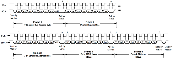
The HDC1000 contains eight registers, whereby five read-only registers solely contain information like the serial ID, the manufacturer ID and the device ID. Hence they are of no interest to us. The remaining three 16-bit registers are listed in the table below.
| Pointer | Reset value | Description |
|---|---|---|
0x00 | 0x0000 | temperature output |
0x01 | 0x0000 | humidity output |
0x02 | 0x1000 | configuration and status |
The natural procedure is now to write the desired settings to the configuration register, then trigger a measurement and subsequently read the measured data from the temperature and humidity output registers. The 16 bits of the configuration register are named in the following way.
| 15 | 14 | 13 | 12 | 11 | 10 | 9 : 8 | 7 : 0 |
| RST | Reserved | HEAT | MODE | BTST | TRES | HRES | Reserved |
We do not want to explain every single pin in detail, but only give the necessary values for measuring both the temperature and the humidity with the maximal resolution of 14 bits. (For a detailed explanation have a look at the datasheet.) Therefore we first write 0x10 as the most significant byte (MSB), i.e. bits 15 : 8, to the configuration register, followed by a zero byte 0x00 for the least significant byte (LSB), i.e. bits 7 : 0.
Now that we have set the configuration, we need to trigger a measurement. This is done by a write operation to the temperature output register, i.e. address 0x00. Simply follow the necessary steps for a write operation as listed above with the 8-bit address in step two being a zero byte 0x00. Step three is omitted. This starts the temperature and humidity measurement, which takes about 13ms for our configuration. As soon as it is finished, the HDC1000 sets the DRDYn line to low, indicating that the MCU can read the measured data.
The DRDYn line is connected to one of the GPIO pins of the MCU, which then exactly knows when to read the measurements. By pulling the GPIO pin of the MCU to low, we can either trigger an interrupt and let the interrupt service routine handle the reading of the data, or we can periodically check for the data ready signal by polling. Since this application is not timing or performance critical, either way works just fine.

Finally a normal read operation at 0x00 will return both measurements. First comes a 16-bit value containing the temperature directly followed by a 16-bit value for the humidity. Remember that we first have to set the pointer register to the temperature register 0x00. Therefore we perform a write operation to the address 0x00 without actually transmitting any data. Subsequently we can initiate the read request. Albeit temperature and humidity consist of only 14 bits respectively, we receive two bytes per observable. In both cases the two least significant bits [1 : 0] will be zero by default. The remaining 14 bits [15 : 2] contain the relevant values. There are simple formulae to convert the obtained numbers to actual temperature and relative humidity. Given the value T[15 : 0] returned by the sensor, the temperature in °C is obtained by
For the relative humidity in percent, we apply
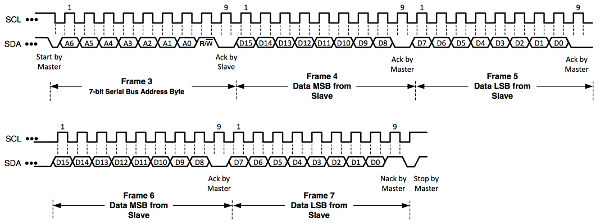
Ambient Light
Apparently ambient light is an important factor influencing a baby's environment. One has to be very careful when it comes to measurements related to light. Often times it is far from obvious, whether one actually records the correct quantity. In this application we do not care about the total power of electromagnetic radiation for example, but only about how bright the environment appears to us as humans. A common photo transistor or photo diode would not suffice in our application, because they respond to all kinds of wavelengths of electromagnetic radiation. In particular, they can not reliably distinguish infrared radiation from visible light. The human eye's sensitivity strongly depends on the wavelength and is given by the so called luminosity function or V-lambda curve. It describes how intense different wavelengths appear to us (while keeping the total power of the radiation fixed). Obviously the V-lambda curve is non-zero only for the visible part of the light spectrum. The maximum lies between 555nm and 570nm depending on whether the eye is adjusted to daylight or night vision.
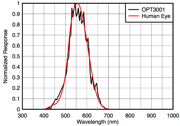
For a reasonable and realistic analysis of the ambient light, we need a sensor that responds to different frequencies exactly like the human eye does. This is the reason, why we decided to work with TI's OPT3001. The figure below shows the impressive agreement of the sensor's response with the V-lambda curve. This plot already indicates the strong infrared rejection, which is probably the most striking feature compared to the naive approach of measuring ambient light with a photo transistor or a photo diode. The OPT3001 filters about 99% of infrared radiation, while photo diodes and transistors are usually highly sensitive to infrared light.
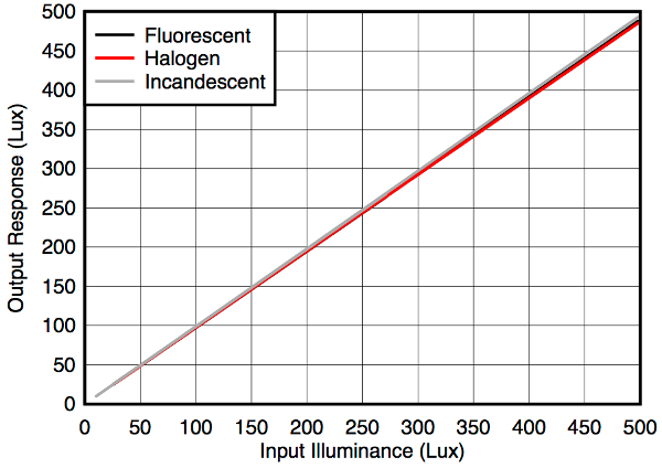
Moreover the OPT3001 behaves quite universal for different light sources, which is shown in the figure below. We see that the input illuminance triggers a linear response, which has a slope that is independent of the originated light source.
The OPT3001 is also connected to the I2C bus, hence the communication is similar to the one we already discussed above for the the HDC1000. We will not go into much detail about the communication protocol anymore, but instead only present the important differences later on. Like the HDC1000, the OPT3001 is a low-power device and spends most of the time in sleep mode. It allows for various complex operation modes, such as performing measurements in certain time intervals and informing the processor about specific events via the INT pin shown in the figure below. However, we do not want to register special events only, but collect data at a precise sampling rate, dictated by the MCU. Thus we trigger measurements externally with the MCU and let the OPT3001 report back when it has finished the measurement via the INT pin. Again, the INT pin is connected to a GPIO pin of the MCU. Of course, the SDA and SCL pins are connected to the I2C bus as always.

Again, the OPT3001 allows us to select one of four different slave addresses, by connecting the ADDR pin to either GND, VDD, SDA or SCL. (Note the minor difference compared to the HDC1000. We still have four different addresses, but only use one pin.) The possible addresses are shown in the table below. We infer that there won't be any conflicts with the HDC1000 on the same bus.
| Address | ADDR Pin |
|---|---|
| 1000100 | GND |
| 1000101 | VDD |
| 1000110 | SDA |
| 1000111 | SCL |
The OPT3001 contains six internal 16-bit registers. Read and write operations are performed analogously to the HDC1000. Besides the two read-only registers containing information about the serial ID and the manufacturer, we have the following four registers.
| Pointer | Description |
|---|---|
0x00 | result output |
0x01 | configuration and status |
0x02 | low limit |
0x03 | high limit |
The low limit and high limit can be used to select the range of operation manually, if one only wants to be alerted, when values lie outside of the given region. The OPT3001 has a total measurement region from 0.01 up to 83000 lux. Because this is a huge range, one needs to specify one of twelve scales before performing an actual measurement. Fortunately the sensor provides a fully automatic dynamic range selection. In this mode the OPT3001 performs a fast ~10ms reference measurement to determine the appropriate range prior to each actual measurement. With this choice, we can use the low limit register for further configurations, while the high limit register is not touched in our application. Writing 0xC000 to the low limit register selects the end-of-conversion mode, i.e. the sensor reports every single measurement as soon as the data is available. (Other options include filtering of certain measurements by the sensor itself.)
We are left with the result and the configuration register. Again, after writing the low limit, we first write the desired configuration to the configuration register. For automatic full-scale setting, an 800ms conversion time (instead of 100ms, which would be more sensitive to noise), single-shot mode (i.e. we do not perform continuous conversions) and reporting the end of every single conversion via the INT pin, we set the configuration register to 0xCA10. (The relatively long conversion time of 800ms is necessary to average out possible 50Hz or 60Hz fluctuations stemming from the mains electricity.) This write operation also triggers a measurement. As soon as the OPT3001 reports the end of the conversion by pulling the INT pin to low, we can then read the result register.
We denote pins [15 : 12] of the result register by E[3 : 0]. They indicate the range that was used in the measurement. Pins [11 : 0] contain the actual result and are denoted by R[11 : 0]. To obtain the ambient light L in lux, we apply the following formula:
Let us sum up the procedure to measure the ambient light.
- Once: Write
0xC000to the low limit register once in the very beginning. - Repeated: For each measurement, write
0xCA10to the configuration register. - Repeated: Wait until the INT pin is pulled to low by the sensor.
- Repeated: Read the result register and compute the corresponding ambient light in lux.
Gas Sensor
While temperature, humidity and ambient light sensing was relatively simple, due to excellent integrated circuit solutions, CO2 detection is more involved. A well established measurement technique is called non-dispersive infrared (NDIR) sensing. It basically relies on shining light through a medium and measuring the transmission spectrum. The absorption as a function of the wavelength allows conclusions about the substances and concentrations present in the medium. CO2 for example has a strong absorption line at 4.26µm. Measuring the absorption at this wavelength enables us to compute the CO2 concentration in parts per million (ppm).
Numerous noise sources and disturbing factors feed into such a measurement. The light source should cover a wide spectrum, but also needs to be very stable. Particularly the wide spectrum suggests a light source based on emission due to heating a metal, instead of power-efficient LEDs for example. This is in stark contrast to our preference for low-power devices in wireless applications. Thus the lamp should by no means be operating continuously, but switched off and back on regularly. A regulated and clean power supply is mandatory. A reference signal is required to eliminate unknown measurement artifacts. The whole procedure is very sensitive to changes in temperature and is hence influenced by the measurement itself. (Switching a light source on and off introduces temperature fluctuations.) One needs to measure rapidly fluctuating voltage levels with high precision in the process of NDIR sensing. Mains electricity will add further noise to the system as well as any switching done to save power. Clean frequency filtering is usually needed to suppress those disturbances. In the end, all those factors make a precise measurement of the CO2 content very challenging, but working with highly optimized ICs actually helps a lot.
There are ready-to-use CO2 sensing solutions available on the market. However for a custom layout design that perfectly fits the final device and for pedagogical reasons, we choose to build the NDIR sensor from more basic ICs. The main part is a configurable analog front end designed for NDIR sensing applications by TI, the LMP91051. Note that although the LMP91051 is not capable of measuring the CO2 content all by itself, it is still a highly elaborate integrated circuit, which provides the basic functionality for a precise NDIR measurement, see the figure below.
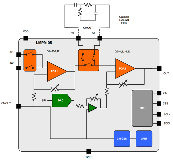
On the right side we see four pins for the synchronous serial peripheral interface (SPI) bus. It is quite similar to I2C and also widely used in embedded systems as a short distance connection. In addition to a clock pin SCLK, and a data pin SDIO, there is also a chip-select pin CSB and a separate digital input/output power supply pin called VIO. We are not going to discuss the SPI protocol in detail, because it can easily be mastered after understanding the I2C protocol. The pins A1 and A0 can be used to connect an external filter (see the figure above), but one can also leave them unconnected for the time being. The CMOUT together with IN1 and IN2 are then used for the actual gas sensor unit. The LMP91051 is well suited for the usage with two thermophile sensors connected to IN1 and IN2, as shown in the figure below. One of them is the active thermophile for the actual measurements, while the other one provides a reference measurement to reduce errors. CMOUT, the common mode voltage output, provides a clean power supply for both thermophiles. Thereby disturbances stemming from varying power supplies are mostly reduced. The last remaining pin is the analog output of the measurement, which is read by an analog to digital converter (ADC) of the MCU.
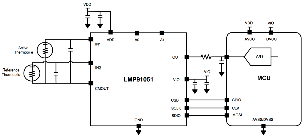
It is still a long way from this basic setup to a reliable measurement of the real CO2 concentration in the air, but with a lot of patience and debugging it is possible, as the parts are perfectly capable of doing the job. Often times, the exact value of CO2 in ppm is not even necessary, but only the evolution, like sudden fluctuations, or extreme deviations from the mean are enough to draw helpful conclusions. Once this is reached, the sensor can easily be gauged to absolute values by a reference measurement in an environment, where the CO2 concentration is known. If gas sensing is required, we suggest reading some application reports and closely following the instructions to get the basic setup to work. From there, one needs to invest a considerable amount of time in optimizing and gauging, until reliable values can be expected.
Heart Rate
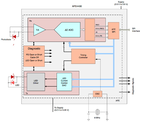
In a future project not only environmental data, but also health data form the baby itself could be included to complement the data stream and consequently generate better and more complete recommendations. The body temperature can easily be obtained by another temperature sensor, positioned close to the baby, for example in direct contact to its skin on a bracelet, or integrated into its clothing. Measuring the heart rate however, is not that simple. Again TI provides an excellent IC called AFE4400, which is an analog front end for heart rate monitors and low-cost pulse oximeters. The basic functionality is similar to the gas sensor we presented above.
The device needs to be in direct contact with the baby's skin. A LED shines light through the baby's veins. Simultaneously the reflected radiation is recorded with a photo diode. While the blood is compressed inside the veins during a heart beat, it changes its optical properties, which in turn is influences the response of the photo diode. From these periodic changes one can compute the heart rate of the baby. The AFE4400 communicates with the MCU again via SPI and provides LED drivers with precise current control as well as a connection pin for the photo diode. An oversimplified block diagram of the AFE4400 is shown in the figure below. Note that with its 40 pins it is quite a monster and it will presumably take a long time until we get it to work correctly.
Now that we know roughly how our sensors work, it is time to have a look at the big picture. In the next chapter we will have a closer look on how to wire up everything. We won't go into details or show schematics of how to wire the environment or baby tracker, since the article is primarily focused on the software side. The current chapter basically contained all hardware related information that we want to share. (After this introduction, the wiring is actually very simple for most sensors.)
Architecture Overview
In the previous chapter we had a closer look at the hardware side. This aspect plays an important role in the overall architecture of the project. To aggregate the information from the previous chapter in one simple picture, we provide the following illustration. The figure sketches the interplay of the MCU with the various sensors. We use two different devices - one for tracking the baby's data and one for tracking the properties of the baby's environment. We call the latter the room tracker.
But this is only a small fraction of the big picture. In reality, we also require a powerful cloud service, which is able to aggregate and evaluate all the data. A proper design of the evaluation tool is obligatory. The 10,000 feet bird-view of our architecture looks as follows. We center everything around a web service, which will be provided by the Azure Mobile service. The backend is mostly concerned with bringing the data to the Azure Machine Learning workspace and running evaluations against the data.

Basically the whole application is divided into three parts:
- Getting the data into the application (to an intermediate location and then to an Azure Machine Learning workspace)
- Conducting experiments and storing the data in Azure SQL
- Accessing the data via applications that communicate to the provided Azure Mobile Services
If we view the architecture as an application we are mainly interested in the data flow. After all any application is only concerned with transforming an initial set of data to a final set of data. Our initial set is the raw sensor data. Our final data is stored in the Azure SQL database or computed on request via some API.
The Application
First we'll have a look at the provided application. The ordinary user only sees and interacts with the representation endpoints, namely the mobile applications and the webpage. For the contest we'll only use a webpage, since distribution, installation and maintenance of mobile applications is more fragmented, cumbersome and personal. The webpage contains everything a normal user cares about. Mainly this is the data that has been supplied by the user. However, we represent the data in an evaluated and educative fashion, making it a personal, enjoyable and informative experience.
For the programmer the RESTful webservice is the most important part of our solution. Since the webservice is also the heart of our architecture, we'll have a look at this part first. We also talk about a special application that is used as a sample data generator. The data generator is the only application that has to be downloaded and run locally. Obviously data is collected and provided by the tracking device in the real application. For testing and demonstration purposes, the sample data generator simulates the functionality of the tracking device.
The Webservice
The webservice is implemented via an Azure Mobile service. This has several advantages. The integration to Azure is excellent, with good flexibility and everything already being set up for us. Since we would like to leverage .NET, we get a very good API and tooling support using the latest Visual Studio release. (The careful reader might realize in the code snippets below, that we are also thinking about adding an accelerometer to the baby tracker. Thus we already provide the necessary interface here.)
Of course we will provide some insight to the transmitted data, however, showing all transmitted data might be a little bit too much. If we sample once per second then we have 86,400 measurements per day. This is far over half a million messages per week. It is far too much to process for a standard client. Therefore the service will only grant access to already averaged data. We will use a moving average (see Wikipedia for more information) to get a sliding window. This will be provided by the Machine Learning API, which will be discussed later. The Mobile Service has direct access to batched averages, which represent aggregates over certain time spans. We use a time span of 5 minutes. This is a good comprise between precision and the number of messages. Here we save a factor of 300. Hence a full year can be loaded in full detail with just 700k messages. Normally, however, we would not send all (aggregated) messages to the client, but again just averages. We would always send a more or less constant number of messages, where the precision of the messages is computed via the requested time span. A full year would loaded with below 200 messages, each representing around 48 hours, i.e. 2 days. A full day would be represented by just 144 messages, meaning that every message accounts for 10 minutes.
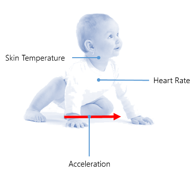
What kind of data do we expect from these sensors? Please note, that the given values do not represent the original sensor data, but the transmitted sensor data. The original sensor data has to be preprocessed by the MCU.
- Accelerometer [g], stored as a
double, where we expect [0 → 5]. Usually around 1. - Heart rate [bpm], stored as a
double, where we expect [0 → 250]. Usually around 135. - Temperature [°C], stored as a
double, where we expect [0 → 70]. Usually around 34.
The figure above illustrates our three sensors for the baby tracker. We will receive data for the heart rate, skin temperature and an optional accelerometer. The heart rate is an obvious indicator of the baby's stress level. It should be emphasized that the base level is different from baby to baby. Therefore our machine learning algorithm has to be able to identify the base level. The skin temperature is different to the core temperature of a human being. This is an important observation. Nevertheless, the skin temperature should be related to the core temperature by just a fixed offset. The offset is practically determined by the thickness of the grease film. Of course the temperature also depends highly on the point of measurement. Our algorithm relies on the condition that the measurements are always taken on the same spot.
A study by Fransson, Karlsson and Nilsson shows that skin temperatures may vary independent of the ambient temperature[15]. The study also confirms that the abdomen is a good position for a skin temperature measurement, as the variation is minimized here. Finally they conclude that for a baby it is very important to have close physical contact with his / her mother for temperature regulation during the first few postnatal days.
Let's have a look at the model for an aggregated measurement:
/// <summary>
/// Contains an averaged measurement of the baby.
/// </summary>
public class BabyItem : EntityData
{
/// <summary>
/// Gets or sets the associated user id.
/// </summary>
public String UserId { get; set; }
/// <summary>
/// Gets or sets the heart rate in bpm.
/// </summary>
public Double HeartRate { get; set; }
/// <summary>
/// Gets or sets the total acceleration in g.
/// </summary>
public Double Acceleration { get; set; }
/// <summary>
/// Gets or sets the skin temperature in °C.
/// </summary>
public Double Temperature { get; set; }
/// <summary>
/// Gets or sets the center time of the considered measurements.
/// </summary>
public DateTime Time { get; set; }
}
The Time property yields the center time of all measurements. This means that for a single measurement get the time of the measurement. For two measurements we get the time of the first measurement, with an additional offset that is half of the time span from the second measurement to the first measurement.
So let's see a picture that's similar to the one before: illustrating the room tracker's sensors.
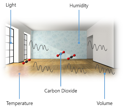
The room tracker measures volume, carbon-dioxide level, light level, humidity and temperature. The humidity and temperature levels are especially interesting. Here we can draw direct conclusions in correlation with the baby's sensor. But also volume and light are very interesting. Light is more or less just a confirmation sensor. Besides variations of day and night we'll most probably confirm the baby's prime sleep time. As far as carbon-dioxide is concerned, we don't know yet what kind of interesting correlations can be computed.
What kind of data do we expect from these sensors? Please note, that the given values do not represent the original sensor data, but the transmitted sensor data. The original sensor data has to be preprocessed by the MCU.
- Humdity [%], stored as a
double, where we expect [0 → 1]. Usually around 0.5. - Temperature [°C], stored as a
double, where we expect [-20 → 50]. Usually around 20. - Volume [dB], stored as a
double, where we expect [0 → 120]. Usually around 60. - Ambient light [lx], stored as a
double, where we expect [0 → 15000]. Usually around 150. - Carbon-dioxide [ppm], stored as a
double, where we expect [0 → 1000000]. Usually around 400.
Let's have a look at the model for an aggregated measurement:
/// <summary>
/// Contains an averaged measurement of the room.
/// </summary>
public class RoomItem : EntityData
{
    /// <summary>
    /// Gets or sets the associated user id.
    /// </summary>
    public String UserId { get; set; }

    /// <summary>
    /// Gets or sets the humidity in percent (0-1).
    /// </summary>
    public Double Humidity { get; set; }

    /// <summary>
    /// Gets or sets the room temperature in °C.
    /// </summary>
    public Double Temperature { get; set; }

    /// <summary>
    /// Gets or sets the volume level in dB(A).
    /// </summary>
    public Double Volume { get; set; }

    /// <summary>
    /// Gets or sets the ambient light in lx.
    /// </summary>
    public Double Light { get; set; }

    /// <summary>
    /// Gets or sets the carbon dioxide level in ppm.
    /// </summary>
    public Double CarbonDioxide { get; set; }

    /// <summary>
    /// Gets or sets the center time of the considered measurements.
    /// </summary>
    public DateTime Time { get; set; }
}
Now that we've explained the basic models for the aggregated measurements, we'll also have to look at some of the other models. For instance we have another model to describe device(s) that have been added by the users of BabyZen. The name of the device is also the one that should be used when sending sensor data. Otherwise the data is dropped immediately. Here UserId and the Name of the device have to match.
/// <summary>
/// Represents a registered device.
/// </summary>
public class DeviceItem : EntityData
{
    /// <summary>
    /// Gets or sets the associated user id.
    /// </summary>
    public String UserId { get; set; }

    /// <summary>
    /// Gets or sets if the device is still active.
    /// </summary>
    public Boolean Active { get; set; }

    /// <summary>
    /// Gets or sets a name for the device.
    /// </summary>
    public String Name { get; set; }

    /// <summary>
    /// Gets or sets a description for the device.
    /// </summary>
    public String Description { get; set; }
}
Another model of interest is the UserItem, which mirrors the additional information about a specific user of BabyZen. We'll store a randomly generated salt and the salted and hashed password. Even if somebody has the salt the password cannot be deciphered. Brute force is practically the only way of retrieving a user's password (and even then there is some chance that the match is actually an overlap, and not the originally given one).
For the given article we do not require a valid mail address. In a productive version of the application a valid mail would certainly be required, however, since we do not use any mail service, or mail server, we couldn't reliably verify a user's mail address. It should be noted, however, that Azure provides mail services, which would work in such scenarios. Finally the IsReadOnly property enables a read-only mode for a user. In this mode the user can still sign-in, but does not have any possibility of altering data. This mode is obviously mandatory for the already prepared demonstration account.Here modifications should be avoided, otherwise an evil user may destroy the experience for other visitors.
/// <summary>
/// Describes a user in more detail.
/// </summary>
public class UserItem : EntityData
{
    /// <summary>
    /// Gets or sets the associated user id.
    /// </summary>
    public String UserId { get; set; }

    /// <summary>
    /// Gets or sets the salt.
    /// </summary>
    public Byte[] Salt { get; set; }

    /// <summary>
    /// Gets or sets the salted and hashed password.
    /// </summary>
    public Byte[] SaltedAndHashedPassword { get; set; }

    /// <summary>
    /// Gets or sets the first name of the user.
    /// </summary>
    public String FirstName { get; set; }

    /// <summary>
    /// Gets or sets the last name of the user.
    /// </summary>
    public String LastName { get; set; }

    /// <summary>
    /// Gets or sets the email of the user.
    /// </summary>
    public String Email { get; set; }

    /// <summary>
    /// Gets or sets if the user cannot modify data.
    /// </summary>
    public Boolean IsReadOnly { get; set; }
}
Now the question is how such a user may identify in the system. The team at Microsoft had one clear answer to this question: OAuth! However, what if a particular user does not want to share his Twitter / Facebook / Google or Microsoft account? What if he does not have an account at one of these companies. So we've wanted to start with a custom login procedure. In the future we may also offer OAuth logins, but for now we keep it open. As the project is still in an experimental phase, we see no disadvantage for such an approach. Indeed there are many advantages for custom logins.
The first thing we need is a custom login provider. This is just a class that inherits from LoginProvider. Any Mobile Services application uses such providers to generate authentication tokens, which are then used internally to ensure a user's authentication. The most important thing in implementing a custom login provider is to provide an unique name.
public class CustomLoginProvider : LoginProvider
{
    public static readonly String ProviderName = "custom";

    public CustomLoginProvider(IServiceTokenHandler tokenHandler)
        : base(tokenHandler)
    {
        this.TokenLifetime = new TimeSpan(30, 0, 0, 0);
    }

    public override String Name
    {
        get { return ProviderName; }
    }

    public override void ConfigureMiddleware(IAppBuilder appBuilder, ServiceSettingsDictionary settings)
    {
        // Not Applicable - used for federated identity flows
        return;
    }

    public override ProviderCredentials ParseCredentials(JObject serialized)
    {
        if (serialized == null)
            throw new ArgumentNullException("serialized");

        return serialized.ToObject<CustomLoginProviderCredentials>();
    }

    public override ProviderCredentials CreateCredentials(ClaimsIdentity claimsIdentity)
    {
        if (claimsIdentity == null)
            throw new ArgumentNullException("claimsIdentity");

        var username = claimsIdentity.FindFirst(ClaimTypes.NameIdentifier).Value;
        var credentials = new CustomLoginProviderCredentials { UserId = TokenHandler.CreateUserId(Name, username) };

        return credentials;
    }
}
The only custom dependency of the login provider is the CustomLoginProviderCredentials. This class is even simpler. We only have to use the same name that identifies the custom login provider. This is also the reason why we created the name as a static readonly field previously:
public class CustomLoginProviderCredentials : ProviderCredentials
{
    public CustomLoginProviderCredentials()
        : base(CustomLoginProvider.ProviderName)
    {
    }
}
With the custom login provider in place we only need to create methods for registration and login. We also may want to create further methods to reset the password, get an e-mail field or some other auxiliary functions. But these are all for convenience and not crucial.
Let's see how a custom registration could look like:
static readonly String userAlreadyExists = "The username already exists";
static readonly String userNameInvalid = "Invalid username (at least 4 chars, alphanumeric only)";
static readonly String passwordSecurity = "Invalid password (at least 8 characters, lowercase characters, uppercase characters, numbers and special symbols required)";

// POST api/registration
public HttpResponseMessage Post(RegistrationAttempt data)
{
    if (!Regex.IsMatch(data.UserName, "^[a-zA-Z0-9]{4,}$"))
    {
        return Request.CreateResponse(HttpStatusCode.BadRequest, userNameInvalid);
    }

    if (!Regex.IsMatch(data.Password, "^(?=.*?[A-Z])(?=.*?[a-z])(?=.*?[0-9])(?=.*?[#?!@$%^&*-]).{8,}$", RegexOptions.ECMAScript))
    {
        return Request.CreateResponse(HttpStatusCode.BadRequest, passwordSecurity);
    }

    var context = new MobileServiceContext();
    var account = context.UserItems.Where(a => a.UserId == data.UserName).SingleOrDefault();

    if (account == null)
    {
        var salt = LoginProviderUtilities.GenerateSalt();

        var newAccount = new UserItem
        {
            Id = Guid.NewGuid().ToString(),
            UserId = data.UserName,
            Salt = salt,
            SaltedAndHashedPassword = LoginProviderUtilities.Hash(data.Password, salt)
        };

        context.UserItems.Add(newAccount);
        context.SaveChanges();
        return Request.CreateResponse(HttpStatusCode.Created);
    }

    return Request.CreateResponse(HttpStatusCode.BadRequest, userAlreadyExists);
}
There is nothing fancy about the method. The incoming model only consists of a UserName and a Password. In the future this may be extended with the e-Mail address, however, at the moment the address is not validated and therefore only optional. Why require entering optional data at login?
What else can be said about the registration method? Maybe the regular expression to check if the given password satisfies the security settings is interesting. We require a mixture of lowercase, uppercase, numeric and symbolic characters. Also at need 8 characters need to be supplied. This should force users to only supply good passwords.
The careful reader may have detected the usage of the custom LoginProviderUtilities class. This is a utility class that gives us methods to generate random byte sequences, hash strings using such a sequence or compare two hashed passwords. Generating the salt pretty much wraps the RNGCryptoServiceProvider class provided by the .NET-Framework. The exact form of the Hash function are not explained in this article due to security reasons.
For signing users in we also need to provide a custom method:
// POST api/CustomLogin
public HttpResponseMessage Post(LoginRequest data)
{
    var context = new MobileServiceContext();
    var account = context.UserItems.Where(a => a.UserId == data.UserName).SingleOrDefault();

    if (account != null)
    {
        var incoming = LoginProviderUtilities.Hash(data.Password, account.Salt);

        if (LoginProviderUtilities.SlowEquals(incoming, account.SaltedAndHashedPassword))
        {
            var claimsIdentity = new ClaimsIdentity();
            claimsIdentity.AddClaim(new Claim(ClaimTypes.NameIdentifier, data.UserName));
            var loginResult = new CustomLoginProvider(Handler).CreateLoginResult(claimsIdentity, Services.Settings.MasterKey);
            return Request.CreateResponse(HttpStatusCode.OK, loginResult);
        }
    }

    return Request.CreateResponse(HttpStatusCode.Unauthorized, "Invalid username or password");
}
This is pretty much straight forward. Again, the LoginRequest model is very simple. In fact it just consists of a username and a password, much like the RegistrationAttempt model before. However, combining both models is not a good idea. They might diverge in the future and it would confuse other developers. They have the same structure at the moment, this is true, but they are not the same thing.
For the moment we are done with our backend. This has now become a simple "What API should be available?" to "Let's integrate it" game. The backend will be extended with Azure ML integration and more later on.
The Web Application
Again we use a solution that offers great support from Microsoft: ASP.NET MVC. We go for a single-page application (SPA), since this provides everything we need in a very modern and lightweight container. The SPA will be build with front-end scripts such as Knockout and Sammy.js. The former is a MVVM framework, which provides a lot of flexibility and familiarity for people coming from WPF. It advocates databinding as it should be. The latter is a very small and useful core framework library. It basically contains a router. But that is really the core what we need. A small tutorial about SPA with Knockout and Sammy.js is given by Manish Sharma on C# Corner.
What we get is an ASP.NET website that comes with an OWIN compatible implementation. OWIN is short for Open Web Interface for .NET and standardizes the interface between .NET web servers and web applications. We great advantage of using an OWIN compatible implementation is the flexibility. We can host our web app on an IIS, however, we may also host it in a Linux environment. There are .NET webservers that can run on Linux from the beginning. A great example is the Kestrel HTP server project, that offers a webserver that is written on top of the popular libuv library. The libuv library is actually the core library for providing asynchronous IO events for Node.js.
Everything up to this point is true. Nevertheless, we won't use much of it. The ASP.NET MVC part is nice to have, but for our web application we will practically only serve static content. All the rest will be exclusively done on the client. This comes at a cost: We will write lots of JavaScript and people with no JavaScript (enabled) won't get to see anything fantastic at all.
Writing such a huge SPA application could be done from the ground up, but we want to boost our development by using amazing third party libraries. We are going to use:
- jQuery, the standard library for abstracting DOM manipulation
- crossroads.js, a library for routing (in combination with
hasher) - signals, it is nice to have a powerful eventing available
- Knockout, which brings MVVM with (web) components to JavaScript
- Bootstrap, a responsive presentation framework
- morris.js, because good looking charts matter
- Font Awesome, since web fonts are awesome and icons need to scale
- RequireJS, which makes dependency management possible
We also some popular jQuery libraries, such as DataTables, the standard validation library that comes with ASP.NET MVC, or metisMenu. All in all that is quite a lot, and at this point it is unclear how many functions of all these libraries will be used. In the end we need to consider some metrics for removing unused code. For the moment we'll accept the possible overhead and welcome the flexibility to use a lot of premade functions with great helpers and professional design.
The plan is to create the web application without relying on the webservice. We will setup all templates, define the viewmodels and create the internal routing. In the end we will exchange the dummy provider / API with our backend connection. At this point everything should be fine. This way it is also possible to do two things in parallel: Create the web application and independently enhance the web service. We'll look on the integration of the Mobile Services API into the SPA later.
What kind of services and views do we want to offer?
- Change your user info
- Reset your password
- See the status of all your sensors
- Add, remove and change sensors
- Add infos about your baby(s)
- Get the Zen factor
- Current evaluation and recommendation
- Next point in time for ventilation
Additionally to the possibilities listed above we also show some data. Here's what we offer:
- Timeline with evaluation
- Skin and ambient temperature depending on time
- Humidity, heart rate and acceleration depending on time
- Baby log data
The baby log is a valueable addition to the whole sensor data. Since each sensor represents one baby, the user can supply additional data called a log. This data is primarily for bookkeeping reasons, however, it can also be plotted. Additionally it may be helpful in the future. Correlations are always interesting.
The Baby's Zen Factor is a scale for the happiness of a child. We rate it from 0 to 10, with 0 being unbalanced and out-of-zen, while a 10 indicates a super positive baby, that is generally very quiet, active and balanced. Currently the rates should be between 6 and 9. We don't know yet if anything would justify a level 10 rating (how does such a baby look like?). We also don't know if there are super unhappy babies at all. For all these cases we need to widen our set of training data.
Internally we split everything up in Knockout components. These are reusable and satisfy our constraints. Let's have a look at our RequireJS configuration:
var require = {
    baseUrl: '.',
    paths: {
        'bootstrap': 'scripts/bootstrap.min',
        'crossroads': 'scripts/crossroads.min',
        'hasher': 'scripts/hasher.min',
        'jquery': 'scripts/jquery-1.10.2.min',
        'knockout': 'scripts/knockout-3.3.0',
        'knockout-projections': 'scripts/knockout-projections.min',
        'signals': 'scripts/signals.min',
        'text': 'scripts/text',
        'MobileService': 'scripts/MobileServices.Web-1.2.5.min',
        'context': 'scripts/app/context',
        'morris': 'scripts/morris.min',
        'metisMenu': 'scripts/metisMenu.min'
    },
    shim: {
        'bootstrap': { deps: ['jquery'] },
        'metisMenu': { deps: ['jquery', 'bootstrap'] },
        'morris': { exports: 'Morris' }
    }
};
Our startup script does not look so complicated. We only register some of the components that have not been registered as pages already. These are reusable and are heavily used in the transmitted HTML code.
define(['jquery', 'knockout', './router', 'bootstrap', 'knockout-projections'], function ($, ko, router) {
    ko.components.register('area-chart', { require: 'components/AreaChart/model' });
    ko.components.register('bar-chart', { require: 'components/BarChart/model' });
    /* ... */

    // Activate Knockout
    ko.applyBindings({ route: router.currentRoute });
});
So how is the router created? Well, as usual we have a JavaScript file that does the magic. In the previous dependencies we've listed the './router', which is actually a file called router.js. This file requires other JavaScript files, again, and looks as follows:
define(["knockout", "crossroads", "hasher"], function (ko, crossroads, hasher) {
    var activateCrossroads = function () {
        var parseHash = function (newHash, oldHash) {
            crossroads.parse(newHash);
        };
        crossroads.normalizeFn = crossroads.NORM_AS_OBJECT;
        hasher.initialized.add(parseHash);
        hasher.changed.add(parseHash);
        hasher.init();
    };

    var Router = function (config) {
        var currentRoute = this.currentRoute = ko.observable({});

        ko.utils.arrayForEach(config.routes, function (route) {
            crossroads.addRoute(route.url, function (requestParams) {
                currentRoute(ko.utils.extend(requestParams, route.params));
            });
        });

        activateCrossroads();
    };

    ko.components.register('Login', { require: 'components/Login/model' });
    /* ... */

    return new Router({
        routes: [
            { url: '', params: { page: 'Login' } },
            { url: 'Login', params: { page: 'Login' } },
            /* ... */
        ]
    });
});
For the moment we concentrate exclusively on the Login component. We do that to illustrate how easy it is to write such decoupled JavaScript code, which allows exchangeable components. First we have some kind of view for the component. The view is basically just HTML code. We've also included some Knockout annotations. These annotations are really unobtrusive - they are just special data-bind attributes.
The following code is responsible for rendering the login form.
<div class="container">
<div class="card card-container">
<img id="profile-img" class="profile-img-card" src="//ssl.gstatic.com/accounts/ui/avatar_2x.png" />
<p id="profile-name" class="profile-name-card"></p>
<form class="form-signin" data-bind="submit: doLogin">
<span id="reauth-email" class="reauth-email"></span>
<input type="text" data-bind="value: username" class="form-control" placeholder="Username" required autofocus>
<input type="password" data-bind="value: password" class="form-control" placeholder="Password" required>
<div id="remember" class="checkbox">
<label><input type="checkbox" data-bind="checked: remember" value="remember-me"> Remember me</label>
</div>
<button class="btn btn-lg btn-primary btn-block btn-signin" type="submit">Sign in</button>
</form>
<p><a href="#/Forgot/Password" class="forgot-password">Forgot the password?</a></p>
<p><a href="#/Register" class="forgot-password">Register a new account.</a></p>
<div class="alert alert-danger alert-error" data-bind="visible: errorMessage">
<a href="#" class="close" data-dismiss="alert">×</a>
<span data-bind="text: errorMessage"></span>
</div>
</div>
</div>
The code might look a little verbose. We use the popular UI framework Bootstrap, which comes with some disadvantages. The generality of the framework is purchased with the cost of having to write a little bit more. However, in the end Bootstrap pages are also highly responsive, which is then again a benefit.
Every component is actually driven by a JavaScript file. The previously posted HTML code is just a template, which is optional. So how does the JavaScript code for the model look like? Again we use RequireJS to ensure all dependencies are loaded.
In the following code we create a view model called LoginViewModel, which has properties with the connection to the previously bound values. Every property is an ko.observable instance, however, for the form submission callback we just use a simple function.
define(['knockout', 'text!./view.html', 'context'], function (ko, template, context) {
    function LoginViewModel(params) {
        var self = this;
        self.username = ko.observable('');
        self.password = ko.observable('');
        self.remember = ko.observable(false);
        self.errorMessage = ko.observable('');
        self.doLogin = function () {
            context.signIn({
                username: self.username(),
                password: self.password(),
                remember: self.remember(),
                success: function () {
                    /* ... */
                },
                error: function (msg) {
                    self.errorMessage(msg);
                }
            });
        };
        self.route = params.route;
    }

    return { viewModel: LoginViewModel, template: template };
});
There is nothing fancy here. Oh, wait. The only thing that is worth noting is also the point, why we've actually drilled until that particular piece of JavaScript. We only dependent on something called context. The context is an abstraction over the real API. We use the Azure Mobile Services library for the connection to the real API. However, the abstraction allows us to exchange the selected file completely. We only need to replace context.js with context.mock.js in the require.config.js file, and everything would run with a mock, instead of the real file.
Being able to exchange dependencies easily is a huge advantage and one of the reasons why RequireJS should be used in the first place. It does not only minimize load time (yes, there are probably more request, however, these may run in parallel and start right from the header - which gives a better time to screen in the end), it is also very structured and convinient. Otherwise one would never know what the dependencies of a certain JavaScript file would be.
Sample Data Generator
One of the problems with the demonstration of our contribution to this competition is the lack of a fully operating device. Even with all the components described above, we still need more time to get everything to a final state in which the device is running without the need for further modifications. Our solution has the advantage of being easy to program and access. The official device is most probably the best way to use our Azure IoT application, however, it is not the only way. Everyone could build some device, connect to our service and start submitting data, which will get evaluated.
To illustrate that process we offer a simple downloadable "simulation" device. It is a console application that simulates data as if the data would have been sent from the MCU in our tracking device. The charm of the application is the possibility to script it and modify its output. For instance, one can easily simulate an increase in the room temperature. The software therefore does not only represent the sensors, but also the environment. It is possible to modify the environment. Such a modification has also direct effects on the sensor readings. In this way we can very accurately simulate the actual behavior.
Custom scripts can be provided, which are then triggered at certain events. The application supports the creation of a schedule to change certain environmental variables at a certain point in time (periodically, if desired). The application has been written in JavaScript. Naturally JavaScript offers excellent support for the evaluation of other JavaScript files. One requirement for our application is some device that runs Node.js. For testing purposes we run the application on a Raspberry Pi model B. Of course the application can be also executed on a standard desktop computer.
We've picked the Node.js platform for the following reasons:
- Node.js provides an event-loop out-of-the-box. This greatly simplifies single-threaded asynchronous programming.
- The application has wonderful cross-platform capabilities.
- There are many useful modules for terminal input / output (coloring, passwords, ...).
- Communication with web services such as Azure EventHubs works just amazingly well.
- We can directly evaluate user-scripts, which makes run-time injection very easy.
In the following paragraphs we'll go into details of developing the simulation software. We will start with an outline of the general application and then explore certain aspects, like the shell implementation, the scheduler and the connection to Azure EventHubs.
The simulation software is basically a simple JavaScript file that will try to modify the data of the following two objects:
var room = {
    humidity: 0.5,
    temperature: 20.0,
    volume: 30.0,
    light: 80.0,
    carbonDioxide: 200.0,
};
var baby = {
    heartRate: 120.0,
    acceleration: 1.0,
    temperature: 33.0,
};
These two objects represent the properties of the room and the baby. A measurement is simply a snapshot of these two objects at a certain point in time. A scheduler will be triggered by the event loop periodically, which then calls functions that may modify the properties of the room and / or the baby.
The application runs in a custom shell. The shell is created with the following lines:
var rl = readline.createInterface({
    input: process.stdin,
    output: process.stdout
});

rl.setPrompt('>>> ');
rl.prompt();

rl.on('line', function(line) {
    var input = line.split(' ').filter(function(item) {
        return !!item;
    });
    var parameters = input.splice(1);
    var cmd = input[0];
    var command = allCommands[cmd];

    if (command) {
        var arguments = [scheduler, room, baby].concat(parameters);
        command.apply(this, arguments);
    } else if (cmd !== undefined) {
        console.log(chalk.red('Command not found. The following commands are available:'));
        console.log(Object.keys(allCommands).join(', '));
    }

    rl.prompt();
}).on('close', function() {
    process.exit(0);
});
There are multiple command line options that prevent the shell mode and execute a custom defined simulation instead. However, usually it is much more convenient to be able to modify the simulations during runtime, which is why running the shell, e.g., in a screen instance, makes more sense than using the simulation as a background process. Nevertheless, as already mentioned, both ways are possible and we might even prefer the background process in some cases.
The application already comes with a set of predefined possibilities to alter the properties of the room and / or the baby. These possibilities are called commands. A lot of general commands can be found in the general.js file. This also illustrates, how such plugins work in general. We export a simple object, which contains the desired commands. Each command is defined via its command name and the command execution. The latter is just a simple function taking at least three parameters. More parameters are optional and will be supplied if specified. There is no way to tell the application that a certain parameter needs to be passed, however, we can always throw an exception or print an error message.
module.exports = {
    'exit': function(scheduler, room, baby) {
        process.exit(0);
    },
    /* ... */
};
The first three parameters are special. They are not provided by the user, but by the application itself. The first parameter is the scheduler. The second and third parameters contain the current state of the room and the baby respectively. Now what is the scheduler? The scheduler is the part of the application that simulates a real hardware tracker. The hardware tracker would try to get updated sensor information periodically. By using the scheduler we can actually manipulate the sensor information. The scheduler is, however, much more. As the name implies, we can use it to schedule the modifications of the environment. In a way the scheduler is similar to scheduled tasks or cron.
Let's see how we can use the scheduler in order to change the temperature uniformly. The heatup-baby command is a good example. First, we also take optional arguments called temperature and time into account. If these arguments are supplied, they are strings. Hence we need some default values and conversion logic. Once everything is set up, we install a job in the scheduler. At every scheduler checkpoint we want to increase the baby's temperature (regardless of any other changes). Finally, we do not want to keep running forever, which is why we specify an additional until criteria.
module.exports = {
    'heatup-baby': function(scheduler, room, baby, temperature, time) {
        var current = baby.temperature;
        var desired = typeof temperature === 'undefined' ? current + 1.0 : temperature * 1;
        var time = typeof time === 'undefined' ? 0 : time * 1;
        var step = (desired - current) / (time || 1);

        scheduler.always(function(dt) {
            baby.temperature += step;
        }).until(function(dt) {
            return --time <= 0;
        });
    },
    /* ... */
};
The criteria will remove the job once the function evaluates to true.
So how are the commands read and updated? Well, consider the following snippet:
fs.readdir(commandDirectory, function(err, files) {
    for (var i = 0; i < files.length; i++) {
        var file = './' + commandDirectory + '/' + files[i];
        extractCommands(file);
    }
});
Here we read the directory contents of the directory containing the commands. We basically assume that every file is a valid command definition. The extractCommands function is no big deal either:
var extractCommands = function(file) {
    var path = require.resolve(file);
    delete require.cache[path];
    var mod = require(file);
    var cmds = Object.keys(mod);

    for (var j = 0; j < cmds.length; j++) {
        var cmd = cmds[j];
        commands[cmd] = mod[cmd];
    }
};
The first two lines will become important in a minute. Let us ignore them for the time being. The rest is concerned with loading the file into a module, extracting all the commands and installing the extracted commands in the existing command dictionary. This is all straight forward and not very special. So what about the first two lines? This is required to allow command-updating during runtime. We do not want having to stop the simulator, when we seek to include an updated command or a new set of commands.
The magic happens in the following snippet:
fs.watch(commandDirectory, function(evt, filename) {
    if (evt === 'change') {
        var file = './' + commandDirectory + '/' + filename;
        extractCommands(file);
    }
});
If we encounter a change event (the only other event is rename), we want to update the contents of that particular module. There is no event for file creation, which means that in case of copy or move we need to touch (i.e. change) the file again. A simple rename does not trigger the module reload cycle. Now it is obvious why we have to invalidate the given file in the cache. Otherwise we cannot perform updates to already included modules. The problem comes from the Node.js system, which uses this setup to increase performance and reduce required module loads.
Installing the application requires Node.js and the node package manager (npm). Then we simply run the following command in the application's directory:
npm install
This will install all dependencies. Running the application is as easy as typing node index.js. On startup the application will check for the credentials. These need to be supplied. They could also be supplied via command line parameters.
Other Applications
For the contest a central webapp seemed to be the ideal solution. Nevertheless, in practice, a mobile application is the way to go. Here we would choose Xamarin to use C# as our programming language. Also every platform should still have its own look and feel.
A desktop version could also be interesting. However, since the program relies heavily on online data, the web application is most probably as accessible as a desktop version. Moreover, it is not constrained to any platform and avoids all installation issues.
In theory we could also just wrap the web application in a native app (using, e.g., Apache Cordova), but the result would not really offer any relevant advantages over a well done web application at the moment. We do not use any smartphone sensors or the camera. Maybe this will be (optionally) added later. That would be the only aspect we can think of, in which a truly native solution would shine more. Some smartphone OS have a very custom API, or are very different to most other operating systems, resulting in a mediocre solution, when trying to use the same API for multiple platforms.
Setting up Azure
Let us recap what kind of services we want to use from the Microsoft Azure offerings:
- Machine Learning (analyze and recommend)
- Event Hubs (process sensor data)
- Worker Role (continuous data distribution)
- Mobile Services (front-end API)
- SQL (store front-end data, e.g., learnings, user data)
- Storage (synchronize Event Hubs, store data for Machine Learning)
- Websites (host ASP.NET MVC website connected to the Mobile Services)
In the following we will look at the setup and basic configuration of these services. We will use the Azure management portal, Visual Studio and PowerShell, depending on the scenario. In general, the Azure management portal is sufficient to create and configure everything. However, creating the appropriate project in Visual Studio will sometimes come with the benefit of also provisioning the relevant cloud resources for us. But then again, in some special scenarios, a few characters in the PowerShell can save us a multitude of clicks.
Let's start with setting up an Azure Machine Learning workspace.
Setup Machine Learning
The Azure management portal gives us the possibility of creating a new Machine Learning workspace. This is basically a canvas for combining data to form analytics. Microsoft uses the term experiment for every data analysis flow that is set up. We see that creating a Machine Learning (ML) service also implies creating a storage service. We should regard this storage service as being isolated from the rest. We will also create another storage service later for a different purpose.
For now, let us simply fill out the form and request a new ML workspace.
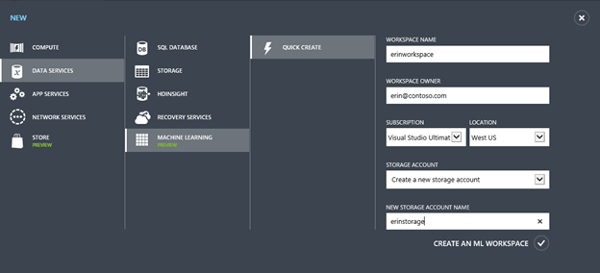
At this point we are basically done. What we could do is logging into the ML workspace and set up one or the other experiment for later.
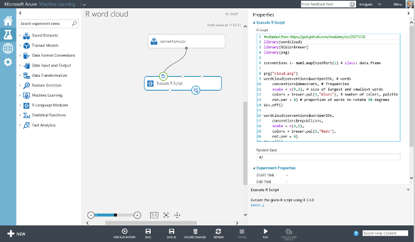
Our plan is to use the created storage service as an inlet data flow for our (upcoming) experiments. The outlet is provided in form of an API, which is automatically used by a worker role, and on-demand by the web application. We will look at the whole idea in greater detail below, in the section about connecting everything together. For the time being we are done with Machine Learning: We set up everything there is at the moment. Thus we can go on and create an Event Hub, which will eventually be utilized by the IoT devices to transmit their data.
Setup Event Hubs
Creating and configuring a new Event Hub is possible via the Azure management portal or via code (e.g. PowerShell, C#, ...). We'll show how to do it via the management portal. Here we follow the instructions given in the starters guide[11].
To create a new Event Hub we click "App Services", then "Service Bus", then "Event Hub", and finally "Quick Create". At this stage we only need to provide the identifier and destination of our new service. It is wise to place the Event Hub in the same data center as the storage service, which we will also require later. If we already have an existing storage account (that could be used), then it is smart to place the Event Hub in the same data center.
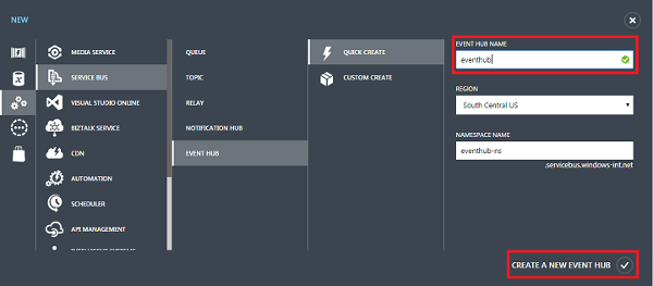
After the Event Hub has been created successfully, we still need to configure it. We actually demand two roles: One for reading from the Event Hub (this will be used only internally) and one for sending new messages to the Event Hub. The latter will be distributed to customers, including people who download the simulator. Hence it makes sense to separate the two roles. For each one we setup an identifier and obtain a key (secret), which is used for authenticating users of the specific role.
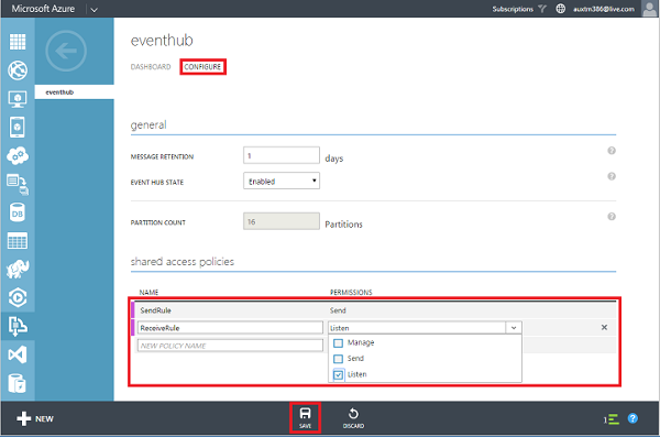
Once all of this is finished, we are basically done with Event Hubs. The rest is just connecting the service, e.g. to our tracker simulator, the real tracker or the listener.
Setup Mobile Services
For the creation of a Mobile service we can use the Azure PowerShell tool:
azure mobile create <service-name> <server-admin> <server-password> --location <data-center-name>
Alternatively we can of course use the Azure management portal. In this case we've chosen still another third approach. We use Visual Studio to conveniently create the mobile service automatically when starting a new project. We begin in Visual Studio with the familiar new project dialog. In the language of our choice (C#/VB) we'll select a new ASP.NET web project. We should see the following dialog or a similar presentation.
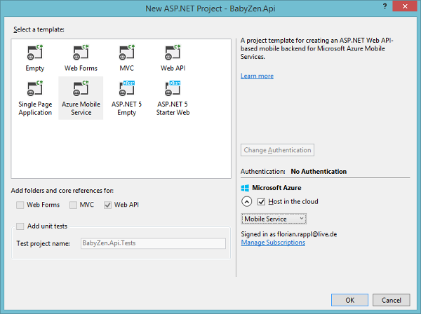
Here we recognize that we have already selected a Web API. We cannot change this selection. What we can do, however, is to select "Host in the cloud". This will give us a few handy possibilities, such as the option to publish the project directly from Visual Studio, without requiring additional configuration.
Since we are willing to host our mobile service in the cloud, Visual Studio brings up another dialog to ask us about specifics of our service. Where do we want to deploy it? What database do we want to use? Do we want to create a new one? Maybe we want to change the responsible subscription. Another important option: What should be the identifier (name) of the service?
The following dialog contains fields that provide answers to all of these questions. The runtime is fixed, since we are already creating a .NET project.
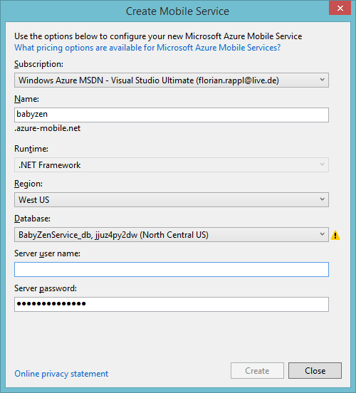
Once we close the dialog, Visual Studio is communicating with Azure and provisioning the new Mobile Services service. At this point we can start with the actual programming. We will go into the details of connecting Azure with our application later. For now, we are done with Azure and Mobile Services. The whole service has already been described in some depth in the application section.
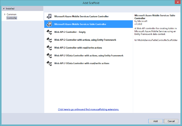
A possible problem with using Azure Mobile Services in the given configuration is the default rule for dropping database tables. Azure will add a special user for the for Mobile Services API in the provided Azure SQL database. However, that user does not have sufficient rights to drop tables. Instead another rule has to be applied.
Since we want to re-create the database in the scenario of a model change (of course this only applies to the current project phase - in production that would be a no-go), we will pick the special ClearDatabaseSchemaIfModelChanges class. This one is much like the ordinary DropCreateDatabaseIfModelChanges class, however, also manages to change everything with the rights provided by the installed Azure SQL user.
public class MobileServiceInitializer : ClearDatabaseSchemaIfModelChanges<MobileServiceContext>
{
    protected override void Seed(MobileServiceContext context)
    {
        /* Populate with some data */

        base.Seed(context);
    }
}
What remains is a short discussion on the possibility of running a Worker Role instead of a web job that comes together with a Mobile Services application. Actually the project template comes with a single predefined web job, so going for a web job seems to be much simpler in the beginning. However, a web job is less flexible, since it is constraint by the boundaries of the Mobile Services offer. Hence something like a background task that is triggered automatically or manually, which uses the same resources as the Mobile Service. Since the Event Hub service is not covered by the Mobile Services application, we cannot easily do that. Adding the most recent version of the ServiceBus library will actually result in an error. This favors Worker Roles, which also have some advantages in terms of scaling.
Nevertheless we use web jobs for other things. We will see later, how we integrated Azure Machine Learning results in our database by invoking the computation via a web job. Here we did not require many resources from the Mobile Services side, however, we loved to build up on our code first database design. Having all tables already defined in code we could directly leverage the power of a tight integration with the Mobile Services application.
Setup Azure Storage
Setting up some Azure Storage is done in no time. Since provisioning some storage is an essential part in many Azure services, it should be obvious that there are many (automatic / API driven) ways to do this. However, in this section we want to illustrate the basic scheme via the Azure management portal.
First we log into the management portal. Then we click "New" at the bottom navigation, following the path "Data Services", "Storage". Finally we give our new Azure Storage some name and pin it to a data center. Optionally, we can select the type of replication for our new Azure Storage. Here "geo-redundant" is the default replication mode. This is alright, as it provides maximum durability.
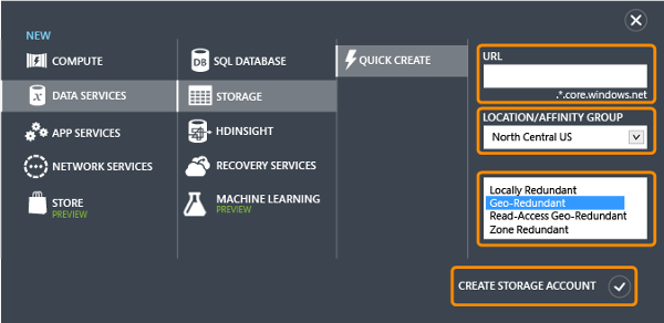
An Azure Storage account comes with several types of supported storage. We can use it to store binary objects in form of BLOBs, store and query documents in tables, setup queues for processing or handle files. In our application we deal with measurement data, which is represented in documents. Therefore we will use the possibilities given by the table storage.
Doing something with Azure Table Storage is as easy as adding the NuGet package WindowsAzure.Storage. Here we get the complete API. The only thing left to do is to provide the connection string to our Azure Storage account. This involves getting the name and the key for the particular service. The name is the one we've entered on setup. The key, however, has not been supplied by us. But we can look it up via the manage keys command at the bottom bar of the management portal. This command is available when selecting an Azure Storage account.
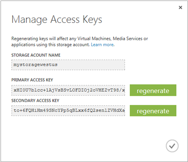
Why are there two keys? It does not matter, which key is being used. There are two keys to allow more scenarios. For instance we could regenerate one key each week for security reasons. To avoid any downtimes or problems we may always alternate between the primary and the secondary key. Before changing, e.g., the primary key, we would set all our services to use the secondary key. Before changing the secondary key in the week after, we would again change all our services to use the primary key beforehand.
There are other scenarios, such as using the primary key externally and the secondary key internally. We will only regenerate the externally used key in such a scenario. We assume that the internal key is save and no one else had any access to it.
Let's move on to a special kind of storage, which is not listed in the storage category at all: SQL databases.
Setup an Azure SQL database
We will need a lot of (preprocessed) data. This data will be highly regular, changing over time, and read multiple times. A SQL database seems like a good idea. There are plenty of options for SQL database systems. We could go wild and operate a virtual machine, where anything could be running. We could also use one of the third party services, such as using a prepared MongoDB instance. There is also the option to rent a full Microsoft SQL Server instance.
For our experimental purposes we don't need terabytes of disk space and hundreds of gigabytes of memory. We need something economic. We need something that provides good performance and offers a well integrated API. Naturally we'll go with an Azure SQL instance. We could create a new instance via the portal, programmatically or in conjunction with a new Visual Studio solution. We decided to go for the third option.
In our case we've got the option to issue a new SQL database on Azure when we created our Mobile Services web service. A dialog similar to the one below has been presented.
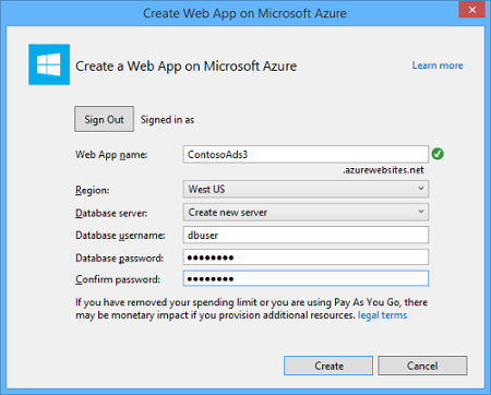
After filling out that dialog Visual Studio is sending the requests to Azure, which will create a new Azure SQL database. The database is already pre-configured and can be used with the Entity Framework library, which is included by default. For efficiency we use a code first approach. This boosts our design and develop process. The only thing to remember is that the ClearDatabaseSchemaIfModelChanges rule will be very destructive in a productive environment. Here we should definitely have a better answer.
Managing the database should not be required (very often). However, it may be reasonable to check the database structure, to see if the code first approach worked as expected. This is especially true in case of any errors. There are multiple ways to connect to an Azure SQL instance. The are the most common ones are:
- Using the Silverlight client from the Azure management portal
- Connecting via the SQL Server Management Studio
- Directly from Visual Studio's server explorer
In any case we need to add a firewall rule. Otherwise we cannot connect to the Azure SQL database from our local machine. Accessing the SQL database from Azure directly will remind us on that. Also an exception will be added automatically, at least if we want to.
In the future Visual Studio could also allow a connection by tunneling through HTTP. However, at the moment SQL databases do not support the OAuth sign-on in Visual Studio. Therefore they still require a management certificate to interact with them in VS. If we right-click the Windows Azure node in the server explorer tree and select "Manage Subscriptions" we can then switch to the "Certificates" tab and import a management certificate. The certificate can be saved in the Azure management portal.
Setup a Website
Setting up an ASP.NET MVC website with Microsoft Azure and Visual Studio is done in practically no time. Here we can fully utilize Visual Studio to do really everything we would normally prepare and execute in the Azure management portal. As with the Mobile Services earlier, we select an ASP.NET Web Application. This time, however, we do not select an "Azure Mobile Service", but rather an ordinary "MVC" application. Most importantly, we check the "Host in the cloud" checkbox. This will give us similar options like the ones we have seen before. Again, Visual Studio will do all the hard work for us.
For our special application we don't need any identity services, as the whole authentication will be handled by the web service. We also don't need any database, as all relevant calls will also be handled by the service. Readers that are particularly interested in deploying ASP.NET MVC web applications with authentication should check out the tutorial from Rick Anderson on the Azure App Service documentation. He describes very well what you can do and how you should do it. We can also learn how to enable SSL for our page.
SSL is also important for us, but not as much as for the scenario that has been described by Rick Anderson. We only load static resources once. There is no security sensitive traffic to the ASP.NET MVC application. Only to the Mobile Services API. And that is HTTPS secured by default. So we are on the safe side. Having HTTPS is still a good thing and indicates security awareness to potential customers.
For the web application we get the same ability as for the Mobile Services backend. We have a special command Publish in Visual Studio. Clicking the command in the context menu will give us options which specify the exact target.
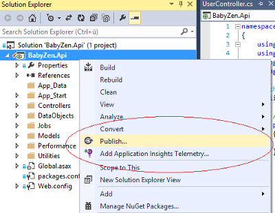
We could also upload our web application via FTP. Or we could use git (or some other supported VCS) to have synchronization as easy as git push azure master. Whatever we want to do, Microsoft got us covered. Of course we selected the Visual Studio way. What could be simpler then code and deploy directly from the IDE? Also most of our other projects are also setup to use the Visual Studio deployment. Consistency is definitely a key point.
Connecting the Services
Now that we've created the various applications we need to connect them. Some of them already "live" in the cloud, others have be published as a cloud service. And all of them need to be connected together. In order to make this as efficient as possible we should have a (secure) document with all the keys, connection strings, names and locations. This really helps a lot.
In the next few sections we will go from our simulator (in form of the provided simulator) to the Machine Learning workspace. From there we will look into the pipe from the workspace to the Mobile Service, which is used by all public applications, such as the web applications. The web application is already completely wired up, by relying on the Mobile Service, which is used via a RESTful API.
The following two images show the two main pipelines. We could draw more pictures like that, but those two pipelines are the most important ones outlined in this article. On the one hand we have a complete processing line from the sensors to the SQL database.

On the other hand we have users who perform (HTTP) requests. We may receive these requests, which starts the second pipeline. Here we want to find the data we've previously stored.

In the next few sections we will deal with the connection between the various bullets in those two pipelines. After all, every bullet has at least 1 neighbor. So communication is required. We'll start by outlining how our simulator communicates with the Event Hub. This communication scheme is similar to the one used in the real device, which, however, is implemented in C.
Sending Messages to Event Hubs via Node.js
Earlier we already described the principles of the software data generator. But one important part of the application was intentionally missing: sending the data.
Finally we also need to send the data from time to time. Here we pick a quite general ansatz, which is described in the blog post "Sending data to Azure Event Hubs from Node.JS using the REST API"[12]. Basically this solution circumvents using the AQMP protocol in the 1.0 specification and uses the optional REST API exposed over the HTTP(S) protocol.
This way we only need to implement one simple function to actually perform the request. We use the popular https module to actually work with the HTTPS protocol. Most importantly we need to post the message. Here we prefer a JSON encoded format, containing the user's identifier as well as the current measurements for the baby and the room, over other possibilities.
var sendData = function(namespace, hub, device, rule, key, user) {
    var path = ['/', hub, '/publishers/', device, '/messages'].join('');
    var hostname = namespace + '.servicebus.windows.net';
    var connectionString = ['https://', hostname, path].join('');
    var sasToken = createSasToken(connectionString, rule, key);
    var payload = JSON.stringify({
        userId: user,
        baby: baby,
        room: room,
    });
    var options = {
        hostname: hostname,
        port: 443,
        path: path,
        method: 'POST',
        headers: {
            'Authorization': sasToken,
            'Content-Length': payload.length,
            'Content-Type': 'application/atom+xml;type=entry;charset=utf-8'
        },
    };
    var req = https.request(options, function(res) {
        // Log and close response
    });
    req.on('error', function(e) {
        // Log
    });
    req.write(payload);
    req.end();
};
There is just one tiny bit that needs further explanation: What is createSasToken? Obviously that function is not part of the https module, nor any other (standard or non-standard) module. We actually added that one to the source code.
SAS is the abbreviation of shared access signatures. It is a powerful way to grant limited access to blobs, tables, and queues to other clients, without having to expose our account key. In case of the Event Hubs REST API, we need to use the SAS in a special form as authorization mechanism. Even if the transmission is somehow intercepted and decrypted (HTTPS is already encrypted), the attacker may not be able to use the connection for a long time. We basically generate different strings and apply an expiration time of one hour. The expiration time is the time after which the SAS is no longer valid.
var createSasToken = function(uri, name, key) {
    // Token expires in one hour
    var expiry = moment().add(1, 'hours').unix();
    var stringToSign = [encodeURIComponent(uri), '\n', expiry].join('');
    var hmac = crypto.createHmac('sha256', key);
    hmac.update(stringToSign);
    var signature = hmac.digest('base64');
    return ['SharedAccessSignature sr=', encodeURIComponent(uri),
        '&sig=', encodeURIComponent(signature),
        '&se=', expiry,
        '&skn=', name].join('');
};
Finally we only need to integrate the functionality of sending the data into the scheduler. The whole process is actually trivial, as we only need to trigger a send operation in certain intervals. Since the scheduler is already trimmed to the usual sending frequency, we will simply transmit data in every iteration.
The following code snippet illustrates the integration.
scheduler.always(function() {
    sendData(queuens, hubname, deviceId, ruleName, secretKey, userId);
});
This way we can easily simulate the behavior of our real tracker. The above procedure also indicates what the device actually has to do. Besides setting up the Wi-Fi connection, which is not hard thanks to the fact that the CC3200MOD is a dedicates chip for IoT applications, one only has to connect to our web service and send the user identifier as well as the baby and room data in the format given above. The MCU is responsible for averaging and preprocessing the sensor data, render it into the desired form and periodically perform a send operation to the web service via our Event Hub.
In order to minimize the energy consumption of the simulation we've decided to place the simulator on a Raspberry Pi. Here we got a lot of benefits and just consume a few watts. In practice we will use ssh to connect to the Raspberry Pi. Then we will open a screen instance, execute up the simulator and detach the screen instance. At this point we can safely log out without killing the process. When we reconnect later, we can easily re-attach the screen instance and use the shell, as if we would have never left it.
Installing Node.js on a Raspberry Pi is not as straight forward as for Windows, Linux or the Mac version. Currently the ARM branch is unfortunately not so well maintained. Also compiling from source will take a long time, since the Pi is just not that powerful (and V8 is a beast). Luckily if we use the Raspbian distribution we can use the instructions provided at adafruit.com. In the end the following commands should do the trick:
sudo apt-get update
sudo apt-get upgrade
wget http://node-arm.herokuapp.com/node_latest_armhf.deb
sudo dpkg -i node_latest_armhf.deb
So we've update the system to the latest version (that's always good), get the latest pre-compiled version of Node.js (for ARMv6) from some (trusted) server and install the Debian package via the Debian package manager. Great! The following screenshot shows the running simulator.
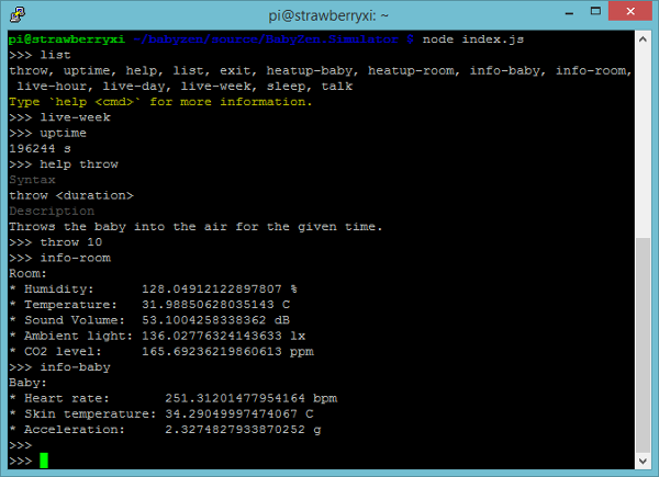
There might be some oddities with outdated Node.js or npm executables. Either we see something like "Illegal instruction" when calling npm, paths that cannot be found or npm install does not find the dependencies (or only outdated versions of them). In any scenario it is wise to have a look at the Ubuntu forum. The error is most probably related to a mixture of Node.js versions. The thread explains how to delete them correctly and how to re-built the systems bindings, such that the current versions are also the ones, which will be executed on demand.
Once everything is running we can observe incoming messages by turning on some event processors, or via the Azure management portal. The usage chart will indicate additional usage. Of course in a productive environment we could not control incoming message numbers. Here we really have to rely on the scaling mechanisms of Azure. Fortunately by using an Event Hub we are already on the save side.

At this point some data is flowing in. The question is: What happens with that data? Azure keeps the data in their partitions. If we want to the data is saved up to 30 days. The default setting is to store the data until one day after transmission. Nevertheless, this data should actually be used. In the next step we will integrate a worker role for moving the data from their current location to an Azure Storage Table, which will work as the input for our Machine Learning application.
Using a Worker Role for Moving Data
For this part we will mainly follow the advices and tutorial, which can be found on the MSDN blog of Kirk Evans. Additionally we use the information on Azure about how to use Table Storage in our application[16]. Equipped with these information we can integrate the services to let the data flow. For a good introduction video on the Azure Worker Role we recommend Channel9[17].
We start by using Visual Studio to kick off a new Cloud Service solution. A Cloud Service is actually a virtual machine, that runs specialized services. One of these services may be a web application. Another one could be a Worker Role. We choose the latter.
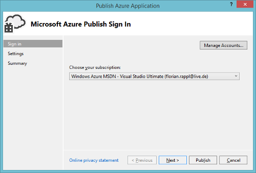
After we've entered the basic data for our Cloud Service we also need to configure additional settings. Here we get the classic options, such as name and location. But we also get other, more specific, options. A Cloud Service gives us the possibility to stage deployment. This allows us to distinguish between a productive application, one that is pre-production and other versions. We can easily exchange that, which embodies a version change. If we really detect something fishy, we can still go back.
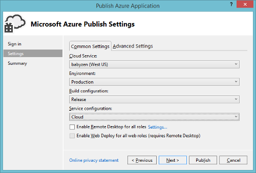
After setting everything up we can choose the various services we want to include. We only pick the Worker Role. We can add more services later. For now the Worker Role is everything we are interested in. Once we are done a new Visual Studio solution is created. The new Visual Studio solution is actually divided into two projects. The first one is the Cloud Service. This is important for providing a configuration and deploying the projects. The second one is the actual Worker Role.
The Worker Role class reads the configuration, creates a new receiver, which starts up the Event Hub aggregation. The data from the Event Hub is received via the DataEventProcessor class, which implements the IEventProcessor. Our code in here is pretty much straight forward, however, please note that we use a custom provider to access the Azure Table Storage, which is accessed by our Azure Machine Learning workspace.
Our processing scheme iterates through all messages, deserializing each message. If the message cannot be deserialized or contains invalid data, we throw it away. If the message does not correspond to a valid user / device combination, then we also drop the message. In any other case we add it to the table context, which queues everything for maximizing efficiency.
sealed class DataEventProcessor : IEventProcessor
{
    readonly TableContext repository;

    public DataEventProcessor()
    {
        repository = new TableContext();
    }

    async Task IEventProcessor.CloseAsync(PartitionContext context, CloseReason reason)
    {
        if (reason == CloseReason.Shutdown)
            await SaveAsync(context);
    }

    Task IEventProcessor.OpenAsync(PartitionContext context)
    {
        return Task.FromResult<Object>(null);
    }

    Task IEventProcessor.ProcessEventsAsync(PartitionContext context, IEnumerable<EventData> messages)
    {
        foreach (var eventData in messages)
        {
            var data = Encoding.UTF8.GetString(eventData.GetBytes());
            var item = JsonConvert.DeserializeObject<DataItem>(data);

            // Check items, create and add entities to context
            /* ... */
        }

        return SaveAsync(context);
    }

    async Task SaveAsync(PartitionContext context)
    {
        try
        {
            await repository.SaveChangesAsync();
            await context.CheckpointAsync();
        }
        catch (Exception ex)
        {
            Trace.TraceError(ex.Message);
        }
    }
}
The incoming DataItem is transformed to two entities, a BabyEntity and a RoomEntity. For example the entity for a measurement of the baby's tracker is shown below. We see that the entity uses some of the same keys in the aggregate before. The UserId, however, is stored as the PartitionKey. This means that we aggregate over users first. Using an efficient scheme is useful for having fast access via the ML workspace.
public class BabyEntity : TableEntity
{
    public Double Acceleration { get; set; }
    public Double HeartRate { get; set; }
    public Double Temperature { get; set; }
    public String DeviceId { get; set; }
}
Finally we also have to look at an interesting point related to our custom TableContext. The TableContext uses instances of StorageTableBuffer<T> for each table of interest. Hence we have StorageTableBuffer<BabyEntity> for the baby measurements and StorageTableBuffer<RoomEntity> for the room measurements.
The only access point is the Include method. We use this method to allow adding items to the buffer. At some point, however, the buffer needs to be emptied. The method ProcessAllAsync triggers this action. But, we need to be sure that the insertation happens correctly. Therefore we are not allowed to go beyond 100 operations in the batch, and we are not allowed to have duplicate keys in the table. The latter should not be possible by design. Another requirement is that all entities in the batch share the same partition key.
The following code satisfies these requirements:
sealed class StorageTableBuffer<T>
    where T : ITableEntity
{
    readonly List<T> _entities;
    readonly CloudTable _table;

    public StorageTableBuffer(CloudTable table)
    {
        _entities = new List<T>();
        _table = table;
        _table.CreateIfNotExists();
    }

    public void Include(T item)
    {
        _entities.Add(item);
    }

    public async Task ProcessAllAsync()
    {
        while (_entities.Count > 0)
        {
            var partition = _entities[0].PartitionKey;
            var operations = new TableBatchOperation();

            for (int i = _entities.Count - 1; i >= 0; i--)
            {
                if (_entities[i].PartitionKey == partition)
                {
                    operations.Insert(_entities[i]);
                    _entities.RemoveAt(i);

                    if (operations.Count == 100)
                        break;
                }
            }

            await _table.ExecuteBatchAsync(operations);
        }
    }
}
The ProcessAllAsync method of each StorageTableBuffer<T> instance is called from the SaveChangesAsync method of our TableContext object. Hence all entities are buffered and executed in batches, as we wanted. Additionally the requirements are satisfied, which should work just fine. Finally we only need to set the configuration, enable logs (very useful!) and deploy our Cloud Service.
The first steps have been quite simple, however, at some point we could not deploy our worker role. We actually faced regular recycling, restarts and crashes. The first reaction to all this problems was to fix the version of the libraries we've included. It seemed that the used Azure Storage library was simply outdated. We wanted to use the most recent version, which is 4.3.0.0. Therefore we included an assembly binding in the app.config. This solution is discussed in greater detail here.
<runtime>
  <assemblyBinding xmlns="urn:schemas-microsoft-com:asm.v1">
    <dependentAssembly>
      <assemblyIdentity name="Microsoft.WindowsAzure.Storage" publicKeyToken="31bf3856ad364e35" />
      <bindingRedirect oldVersion="0.0.0.0-4.3.0.0" newVersion="4.3.0.0" />
    </dependentAssembly>
  </assemblyBinding>
</runtime>
This did not the whole trick. Debugging the application locally revealed that the configuration could not be read. This is bad. This is where we discovered that the Azure ConfigurationManager library is still in version 1.8.0.0, which is outdated. We upgraded to version 2.0.0.0, which was a part success. At this point the configuration could be read successfully, however, running batch queries did throw an exception. The inspiration for this action came from this thread at StackOverflow.
So what was the root of the error for the batch queries? Well, it turned out that the primary key was actually duplicated. By mistake we've chosen a Partition Key - Row Key combination that allowed duplicates. This was actually quite foolish. In the end we decided to use a very reliable combination.

At this stage it seems reasonable to confirm that the data is really flowing in the desired Azure Storage Table. A good tool to view and query the Azure Storage Table is the Azure Storage Explorer. It can also be installed with the popular package manager Chocolatey. The screenshot below shows the program. We can also use the Azure Storage Explorer to create, edit, delete or view entries. The same applies of course to tables. This was very handy for deleting all entries of a table. Instead of deleting all entries directly, it was much easier to use the application to delete the full table at once. This is also more efficient.
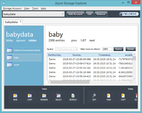
Another good insight can be gained by exploring the dashboards of the Azure Storage target and the responsible Cloud Service. For the Cloud Service we might also be interested in the status of our Worker Role. We demand a busy service without any exceptions. Everything else may indicate some problem.
Sometimes we may also want to restart the service. This can also be done from the management portal. Restarting the service may not make sense if everything is fine and we have some workload, however, it may be wise to do that when there is no workload.

Finally we are done with moving the data from the Event Hub to the Azure Table Storage, where it will be accepted by our Machine Learning algorithms. This will be discussed in the next section.
Publish a Machine Learning API
For the next step we'll need to go back to the data, create experiments and publish these experiments as a web service. All these steps can be done via the Machine Learning workspace. The first thing we do here is insert a Reader object, which can be connected to the Azure Table Storage. This is where the real work starts. We need to figure out what operations should be executed (and in what order). After we set up an experiment we run it against some (current) data and evaluate if the outcome is as expected, or just good enough.
Now we can click the button to prepare the experiment for being exposed as a webservice. We have the command buttons at the bottom to start creating a webservice.

The only thing that changed is that we included two new operations in our experiment. One operation is optional income from the webservice request. The other operation is the outcome from the experiment. We will use the income to distinguish between, e.g., different users, different devices or different time spans. This all depends on the concrete experiment.
A great resource for learning about experiments or getting a fantastic boilerplate are the provided samples. The available collection is large and good enough. It contains for instance basic recommendation samples, which are good enough to create something like a link recommendation system. An example for a successful adoption is given by the guys at Channel9. They blogged about Channel 9 Implements The Azure Machine Learning Recommendations API. For the most parts we follow their approach. We provide services, which are called periodically by web jobs in our Mobile Service.
However, before we can go into details of our implementation, we still have to publish the webservices. Once we prepared the webservice publication the command bar at the bottom changed. Now publishing a webservice from the Machine Learning workspace can be done via the button that is marked in the red square.

We get an API key for every Machine Learning webservice that we publish. This is important for regulating the access to our API. In the end the invocation for conducting experiments is associated with renting Azure computation time. Hence we may be in trouble if anyone could issue an infinite amount of API calls. This is one of the arguments for only calling the API internally. The result will be cached and can only be accessed via the Mobile Services API, which is publicly available and restricted to users of the BabyZen application.
After successfully creating the webservice we also get an overview of the service's information. We see that the webservice is basically built on top of the ASP.NET MVC Web Api. The webservice also comes with the same help page as other ASP.NET MVC based applications. We can also run tests against the webservice.
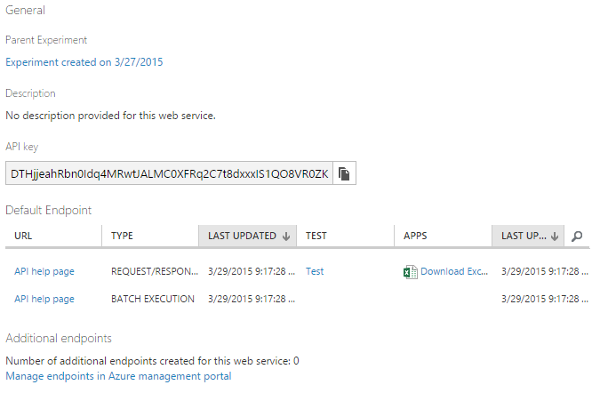
Let's head over to look on the integration of such a webservice with our Mobile Services.
Integrate Machine Learning in Mobile Services
The integration of Machine Learning in Mobile Services is, as a matter of fact, as easy as the general integration of a webservice exposed by the Azure ML workspace into an existing C# application. We already get snippets for talking with the generated service in C#, R and Python. We just need to go to the help pages of our API and we'll find code snippets for all three platforms.
The image below shows how this looks in practice. We always get a lot of boilerplate code. Needless to say that we will most probably change the code a lot.
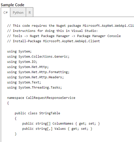
The only thing that's actually missing from the provided snippet is the API key. This is due to security reasons. Therefore, even if we want to keep the originally copied source code, we still have to insert the key. Otherwise nothing will work.
So what have we done in this section? We set up a few Machine Learning algorithms and we selected useful parameters of them to be exposed as an API call. Then we created some ScheduledJob classes, which access these APIs with information from the database. For instance the currently available users form an interesting input parameter. Finally we write the output in some tables.
We are far from being finished here, actually. There is a lot of fine-tuning and we don't know if everything is working as it should be at the moment. The infrastructure site seems to be alright, however, the machine learning algorithms may need a few more tweaks to work as expected.
Integrate Mobile Services in ASP.NET MVC
For the Mobile Services API we've also integrated custom authorization, as described in the Azure documentation[13]. The advantage is that anyone can login. Our MVC homepage is basically reduced to a client-side only website. That ensures high speed with less duplication on the server side. Most API calls can directly use the Mobile Services API, however, others have to go over the more general API.
Before we can do anything with the Mobile Services JavaScript library we need to create a new MobileServiceClient. The constructor demands the host of the API and the access key for it. The code may look similar to the following one:
var client = new WindowsAzure.MobileServiceClient(
    "https://babyzen.azure-mobile.net/",
    "The API key"
);
The API distinguishes between more general API calls (expressed by ApiController subclasses) and table API calls. The latter are based on TableController instances. Note, that it is possible to call all APIs with the general API method as well. Calling a more general API is illustrated with the following code:
var apiName = 'test';
var options = { method: 'GET' };
client.invokeApi(apiName, options, function(error, response) {
    console.log(response.responseText);
});
The invokeApi method requires the name of the API and some options. If no options are supplied then the POST method is assumed. This may be right in some cases, but definitely not always. It is therefore a good practice to supply the options in any case.
The more general API is also crucial for our login process. Since we use a custom login, we have to use a more obscure way of performing the login. We need to set the currentUser manually.
var signIn = function(username, password) {
    var apiName = 'signin';
    var data = {
        username: username,
        password: password
    };
    var options = {
        body: data,
        method: 'POST'
    };
    client.invokeApi(apiName, options, function(error, response) {
        // Check if response is 200 and no error is given
        var user = JSON.parse(response.responseText);
        client.currentUser = user;
        client.mobileServiceAuthenticationToken = user.authenticationToken;
    });
};
The provided login method does not work with our custom login process. At least I could not make it work, however, maybe I did not setup the custom login process correctly. At least with the provided code it seems to work, despite not being very elegant.
Testing the whole process would be very nice. Of course unit tests for the business logic and some integration tests are important, but right now we are only interested in some small and direct tests. Can we access our Mobile Service at all? Can we insert and retrieve data? We can use the included online API documentation to make some test calls. However, since nearly all of our calls are restricted, we need to supply the user information. This does not seem to be trivial, at least there was no official guidance on how to do that. Nevertheless, it is possible, by supplying custom HTTP headers. To make an authenticated request to our API, we need to include the authentication token as an HTTP header named X-ZUMO-AUTH with the request.
The following screenshot illustrates this. Please note that the actual value for the header is dependent upon a prior login request. We cannot always use the same value.
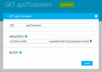
Now the real deal is reading tables. Most of our APIs are given by such tables. And most of them are just queryables. To get all data from a specific table, e.g., device, we can issue some statements like the following. We could use start with some where, select, skip or similar method. With the provided code we get all items from the table. The result is a JavaScript array.
var dev = client.getTable("device");
dev.read().done(function(res) {
    console.log(res);
});
We integrate the methods in our existing app. Now the data is populated automatically. We've already attached all the Knockout observables before, meaning that the application is automatically in a good state. No more data plumbing needed.
Wire everything together
On our way we've made some decisions that provided a shortcut in some sense or that adjusted to real world conditions. Even though only the latter ethnic should be pursued in productive environments, we all know that shortcuts are always taken. Nevertheless, we hope that we've always indicated shortcuts correctly and that we've always suggested more stable, reliable and secure ways of implementing features. A really good guide about writing real world applications for Azure is available on the ASP.NET website[14].
So now we are already close to the grand finale. We have all our services up and running. We have connected them all. The only thing that is missing is a canvas to demonstrate the application. Well, the next section will go show the outcome of the demo application. For now we are more interested in what's happening inside. The Azure management portal is showing us the status of our services. They all look fine.
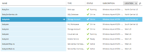
Let's recap the way the data flow once again. We have an unknown number of devices sending data. Usually we would say we have a maximum of one device per user, however, we all know that some people may send data, even though they do not have any account. Maybe these are just bots. Maybe these are evil users. All we know is that anyone could send data to the endpoint. Our Event Hub is there to collect all the data and put it in some partition.
This is where our Worker Role is kicking in. The Worker Role is trying (and therefore probably scaling) to work on the received data. It examines the validity of the transmission and stores the data in an Azure Table Storage. Here only valid and approved data will be saved. This is also the place that is directly accessible from the Azure Machine Learning workspace.
We set up some experiments that can be accessed in form of webservice. The keys are only distributed internally. The only consumer right now is the Mobile Services backend, which invokes some scheduled jobs from time to time. The scheduled jobs run Machine Learning experiments from their API with input from the Azure SQL database. The result is stored in the Azure SQL database. The only accessor to this database is the Azure Mobile Services backend.
The backend is our webservice. It is the API that every BabyZen (front-end) application has to use. That could be mobile apps, desktop or Windows Store applications. For now we've set up a simple ASP.NET MVC page, that is reduced to a single-page application. We call the Mobile Services directly from the client, without having the ASP.NET MVC backend in between. This ensures speed, safety and agility. Less friction means more energy efficiency. However, we'll always need some friction to get some work done.
The Application (Demo)
The web application is a live demo for the infrastructure. There may be down times or unexpected errors. This is still an experimental project and we want to take this further. There will be some testing, so please don't expect it to be available all the time. Also the functionality may break for short intervals.
The figure below shows the dashboard. The dashboard is the view every users gets after a successful login. It shows the most important values.
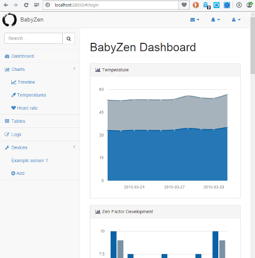
In order to supply a good user experience we also supply a login dialog. In the future people may also request forgotten passwords. Right now this feature is not implemented. There are some missing features, but these features should be available soon. In the future other features will be added as well.
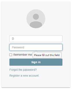
If you want to try out the simulator you must also register your own account. The registration form is shown below.
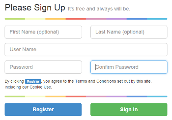
Most importantly the web application can be used to determine the current "Zen Factor". The Zen Factor has been explained in the section about The Web Application. For the screenshot we've indicate a score of 8, which is quite high.
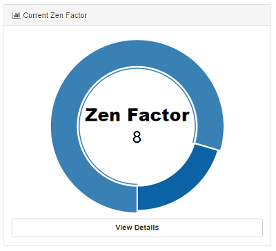
The web application is can be accessed at babyzen.azurewebsites.net.
A demo account for the user Demo with the password Demo$123 is provided. This account is, as already mentioned, read-only, i.e. nothing can be modified. The account is only available as a proof of concept, showing that everything described in here works and is online.
TL;DR
We have build the infrastructure for an application called BabyZen. The application consists of an accessible front-end, and a tracker, which combines a variety of sensors. The idea behind the application is to identify certain patterns in the environment of a baby. The identification of these patterns leads to suggestions about possible improvements. These improvements should prevent illness, enhance the child's development and also benefit the parents directly by minimizing the child's requests. After all, no request is necessary, if the package is already delivered.
A great analogy to our project can be found in the Simpsons's episode "Brother, Can You Spare Two Dimes?"[18]. In the episode Homer's half brother Herb Powell is building a baby translator. This is a device, which translates a baby's mumbling to form a demand or request. Our device is similar, but does not rely on a baby's mumbling, but rather on his or her surrounding. Also we've split the device into three parts: a sender (the tracker), a receiver (Microsoft Azure) and a display, which can be anything from a website to a mobile device or any other application connected to our service.

The device may not look very fashionable, but it is just a prototype. Since such a device cannot be just downloaded, we've decided to write a simulator, which can be downloaded. It is possible to create an account and start sending simulated data. However, please note that simulated data is not restricted to real boundaries and may therefore result in invalid suggestions. We try to detect invalid data, but at this point our algorithms are not trained well enough.

By using Machine Learning algorithms we can use already inserted, categorized and structured, data to train our application. In the end we are able to make certain predictions. At the moment these predictions suffer from the insufficient amount of training data, however, in the future this will most certainly change.
Points of Interest
The BabyZen application provides an enjoyable experience for parents, who want to minimize risks by exposing their children to improper environmental conditions. Of course, great devices with advanced capabilities are required to reliably monitor the required data, but without a flexible and powerful backend the necessary analytics cannot be done. The Microsoft Azure platform provides all the capabilities we need to set up a truly great IoT solution.
Using the device simulator is definitely an interesting experience that can already give us valuable insights. The included commands provide the base for simulating quite a couple of interesting weeks in a normal baby's life. There is a command that will simulate fever, another one dealing with diarrhea and so on. Of course we've also included commands to simulate normal days and ordinary nights. But in the end, one of the most critical targets of the simulation is to decide, whether edge cases can be detected. In our own simulations we've made runs against data gathered from real babies. We found out that the recommendations work exactly as predicated. However, a recommendation system should never be tested against normal or expected data only, but also against all kinds of unexpected data and edge cases.
If you want to play around with the simulator then don't forget to adjust the settings.json file. It contains the user information. These have not been adjusted for you or your BabyZen account. Invalid data will be dropped from the Event Hub as explained earlier.
As always, there are still some remaining questions, which will most probably be answered in the next couple of months: Does the scaling work as expected? Can the real tracker device be seamlessly integrated into the average parents' and baby's daily routine without causing any practical issues and discomfort? (This of course will strongly depend on the exact technical specifications and design of the device.) What other data might be interesting to improve the recommendations? How much impact do our suggestions have? What is the best way to actually recommend actions? The list of questions is basically never ending, which shouldn't come as a surprise, regarding our ambitious goal.
We want to thank everyone who supported this project. Our special thanks to the people at Texas Instruments, who supplied us with sample ICs and free tools. We also want to express our gratitude to Microsoft for providing an awesome collection of tools, libraries, services and infrastructure for free (at least for non-commercial purposes).
References
- Wikipedia: Zen
- Stanford University: Center for Infant Studies
- Yale University: Child Study Center
- The International Society on Infant Studies
- CC3200MOD SimpleLink Wi-Fi and Internet-of-Things Module Solution, a Single-Chip Wireless MCU
- HDC1000 Low Power, High Accuracy Digital Humidity Sensor with Temperature Sensor (Rev. A)
- OPT3001 Ambient Light Sensor (ALS) (Rev. B)
- LMP91051 Configurable AFE for NDIR Sensing Applications (Rev. B)
- AFE4400 Integrated Analog Front-End for Heart Rate Monitors and Low-Cost Pulse Oximeters (Rev. H)
- CC3200MOD SimpleLink Wi-Fi and IoT Solution With MCU-Module LaunchPad User Guide
- Get started with Event Hubs
- Sending data to Azure Event Hubs from Node.js using the REST API
- Get started with custom authentication
- Building Real-World Cloud Apps with Azure
- Temperature variation in newborn babies: importance of physical contact with the mother
- How to use Table storage from .NET
- Channel9: Introduction to Windows Azure Worker Roles
- Wikipedia: Brother, Can You Spare Two Dimes?
History
- v0.9.0 | Initial Release | 30.03.2015
- v0.9.1 | Layout update | 30.03.2015
- v1.0.0 | Added missing sections | 31.03.2015